Charging system and charging method thereof and battery pack

Inactive Publication Date: 2016-03-31
CHERVON HK LTD WANCHAI
View PDF6 Cites 23 Cited by
  • Summary
  • Abstract
  • Description
  • Claims
  • Application Information

AI Technical Summary

Benefits of technology

[0008]The objective of the present disclosure is to provide a charging system an

Problems solved by technology

Because of the limited power endurance of the battery pack, it is necessary to replace the battery pack frequently or charge it.
However, in many instances, it is impossible to charge the battery pack due to the lack of a power interface in an environment.
Thus, it cannot always be ensured that electrical tools being used in some special environments are provided with power for a long period o

Method used


Image

  • Charging system and charging method thereof and battery pack
  • Charging system and charging method thereof and battery pack
  • Charging system and charging method thereof and battery pack

Examples


Embodiment Construction

[0060]The embodiments of the present disclosure will be described herein below in connection with the appended draws in detail.

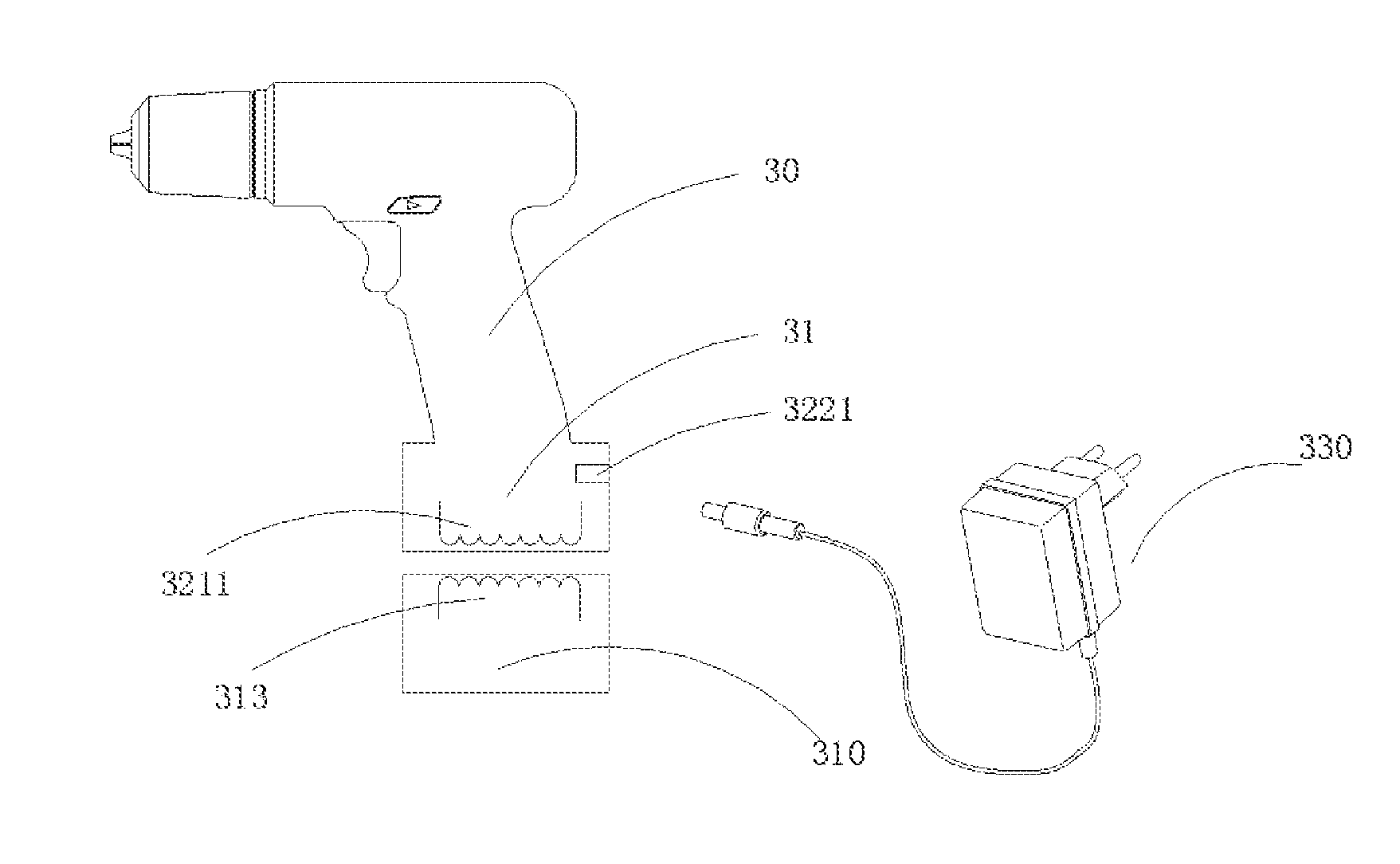
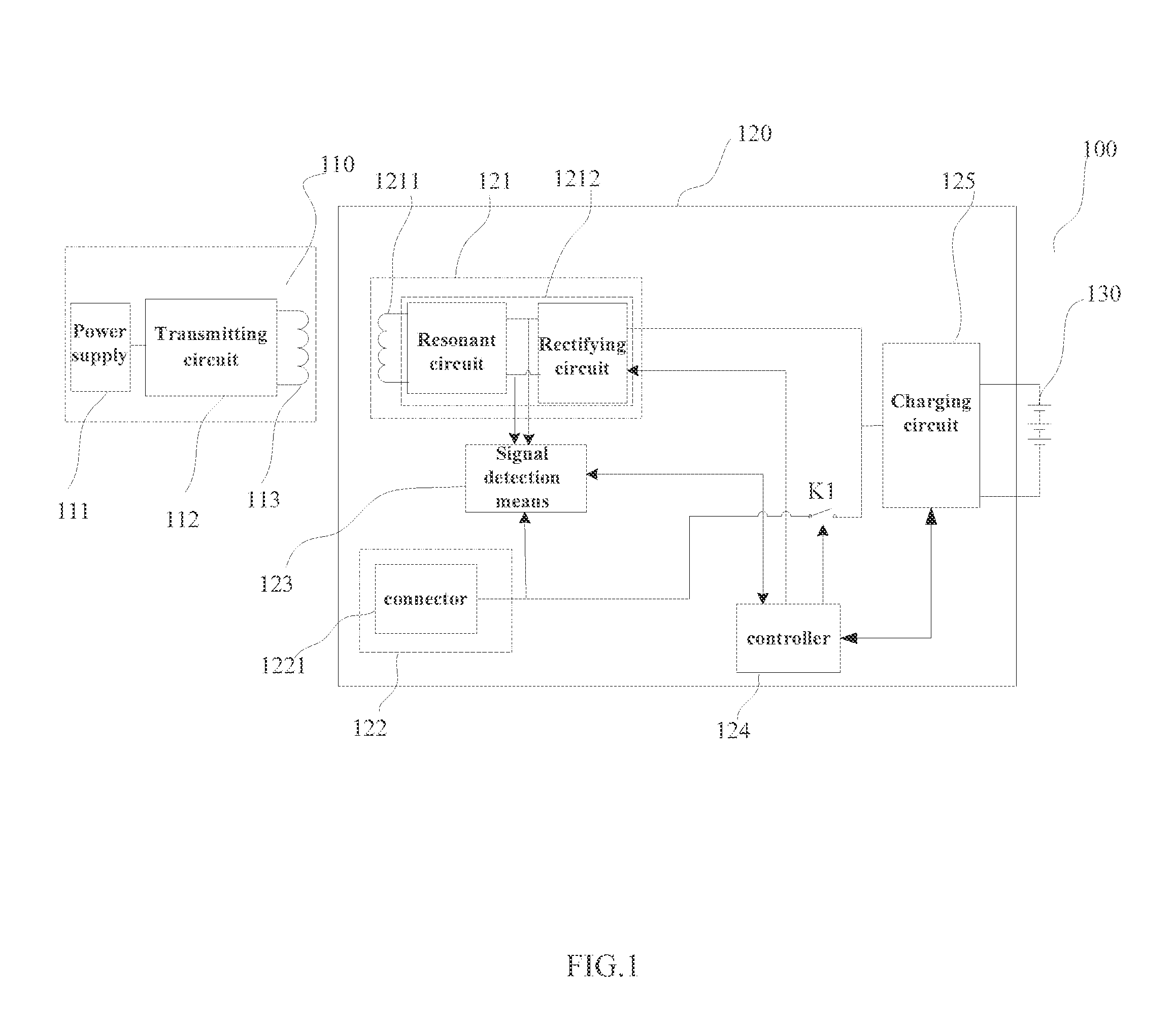
[0061]A schematic diagram of an exemplary circuit of a charging system 100 is shown in FIG. 1. Referring to FIGS. 1 to 3, one of ordinary skill in the art will readily recognize that the wireless power transmitter 110 comprises a power supply 111, a transmitting circuit 112 and a transmitting coil 113, wherein the transmitting coil 113 is electrically coupled to the transmitting circuit 112. The power supply herein generally is an AC power supply. The alternating current will convert into a direct current for charging other modules in the system through use of an AC-DC converter in the transmitting circuit when the AC power supply is coupled to the charging system. It is understood that the technology of wireless charging is well known in the art, which mainly includes an electromagnetic induction mode and / or a magnetic resonance mode. Electromagnetic induct...


PUM


Abstract

A charging system includes a wireless power transmitter configured to transmit electromagnetic energy, a wireless power receiver, a wired power receiver, a signal detection means configured to detect whether power is supplied from a wireless power supply and/or from an external, wired power supply, a controller configured to manage power channels in accordance with states of wired and/or wireless power supply detected by the signal detection means, and a charging circuit configured to receive power energy from the wired or wireless power supply for charging a battery.

Description

CLAIM OF PRIORITY[0001]This application claims priority to Chinese Application No. 201410512459.X, filed on Sep. 29, 2014, Chinese Application No. 201410513244.X, filed on Sep. 29, 2014, Chinese Application No. 201410514023.4, filed on Sep. 29, 2014, and Chinese Application 201410514417.X, filed on Sep. 29, 2014, the disclosure of which are hereby incorporated by reference.BACKGROUND OF THE INVENTION[0002]1. Field of the Invention[0003]The present disclosure generally relates to the field of battery charging and, more particularly, to a charging system and method which can charge a battery in various manners.[0004]2. Description of the Related Art[0005]An electrical tool powered by a battery pack is generally charged by a charger through a wired interface or a power connector. Because of the limited power endurance of the battery pack, it is necessary to replace the battery pack frequently or charge it. However, in many instances, it is impossible to charge the battery pack due to t...

Claims


Application Information

Patent Timeline
IPC IPC(8): H02J7/02H01M10/44H01M10/46H02J7/00H02J7/04
CPCH02J7/025H02J7/04H01M10/441H01M10/46H02J7/0042H01M10/4257H01M10/44H01M10/48H01M2010/4271H01M2010/4278H02J7/0044H02J50/80H02J50/12Y02E60/10
Inventor DONG, AIXIANG
Owner CHERVON HK LTD WANCHAI
Why Eureka
Try Eureka