Mobile robot

a mobile robot and robot technology, applied in the field of mobile robots, can solve the problems of easy interfacial contact between the parts of the mobile robot and objects in the external world, easy interfacial contact between the legs and the external world, and easy interfacial contact between the legs and the external world, and achieve the effect of accurate travel

Inactive Publication Date: 2016-04-07
HONDA MOTOR CO LTD
View PDF0 Cites 9 Cited by
  • Summary
  • Abstract
  • Description
  • Claims
  • Application Information

AI Technical Summary

Benefits of technology

[0018]The present invention has been made in view of the background described above, and an object of the invention is to provide a mobile robot capable of accurately traveling while avoiding the interference with an external world object or the like in a variety of environments.

Problems solved by technology

Hence, if the mobile robots are operated in a variety of environments, then interference between the parts of the mobile robots and objects in the external world tends to take place.
Therefore, when the mobile robot is instructed to climb up a relatively high step or to climb up or down a ladder or a stepladder, the leg links easily interfere with the step, the ladder or the stepladder.
Further, when the mobile robot is instructed to travel on, for example, an irregular terrain or the like in a state in which the mobile robot supports its own weight by the leg links and the arm links thereof (hereinafter referred to as “the multi-legged state” in some cases), the middle portions of the leg links tend to interfere with projections on a floor or the base body thereof.
Thus, a situation in which it is difficult for the mobile robot to travel frequently occurs.
Inconveniently, however, such a solution will easily result in a complicated construction of each leg link or an increase in size or weight of each leg link to enhance the rigidity of the leg link.
There will be another inconvenience in which the singularity state of the leg links easily occurs.
In many cases, the movable range of the distal end portions of the arm links on the rear side of the base body inevitably becomes limited.
Further, if the mobile robot is instructed to climb up or down a ladder or the like with the rear side of the base body thereof facing the ladder or the like, or when the mobile robot is instructed to travel in the multi-legged state, it will be usually difficult to properly move the arm links.

Method used


Image

  • Mobile robot
  • Mobile robot
  • Mobile robot

Examples


Embodiment Construction

[0080]An embodiment of the present invention will be described below with reference to FIG. 1 to FIG. 13.

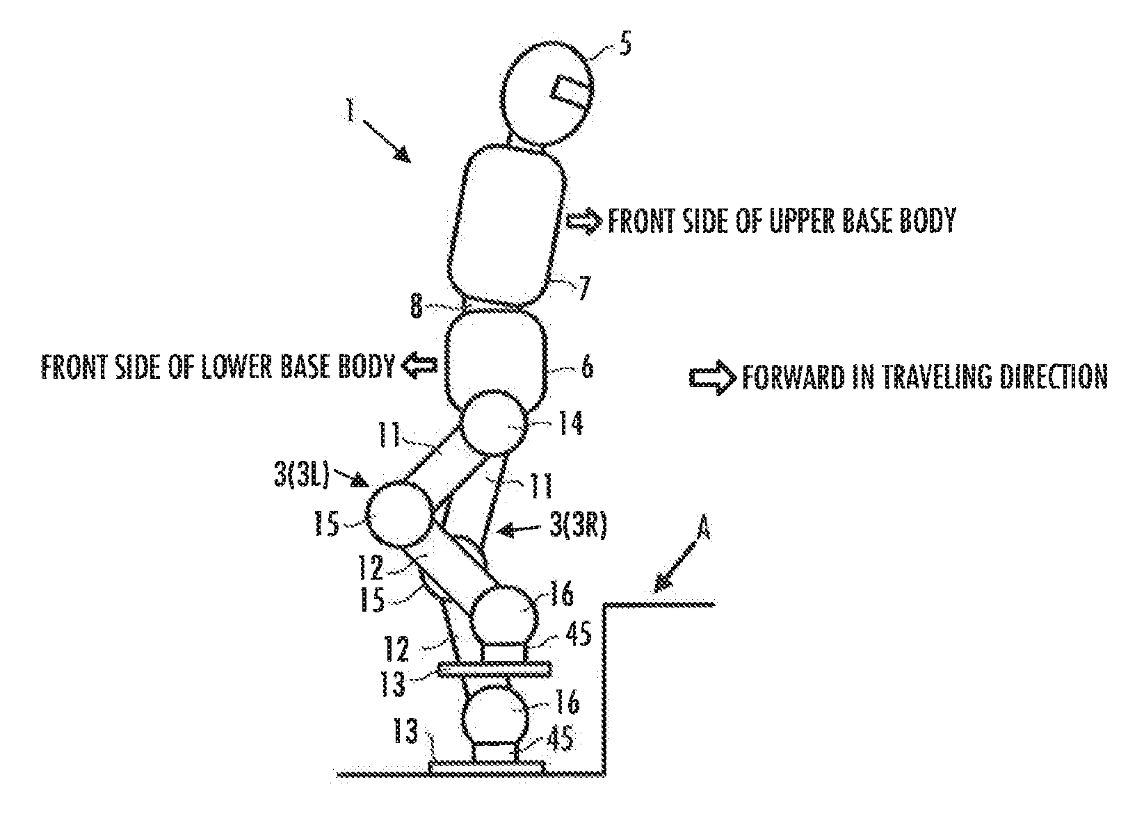
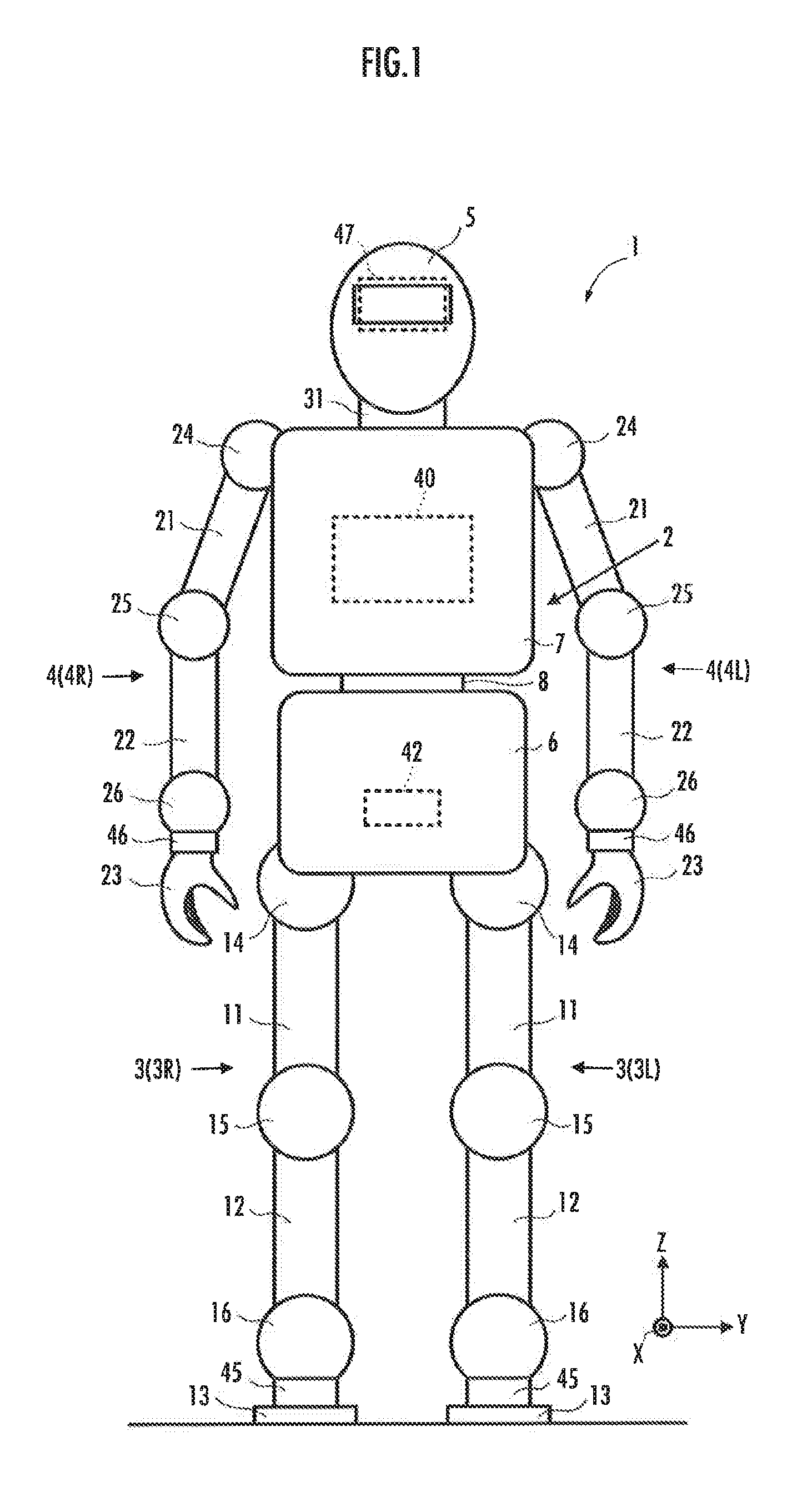
[0081]Referring to FIG. 1, a mobile robot 1 according to the present embodiment is an example of a humanoid robot. The mobile robot 1 (hereinafter referred to simply as “the robot 1” in some cases) has a base body assembly 2 corresponding to an upper body, a pair of left and right (two) leg links 3L, 3R and a pair of left and right (two) arm links 4L, 4R, which serve as a plurality of movable links connected to the base body assembly 2, and a head 5.

[0082]In the description of the present embodiment, the reference characters L and R used in the leg links 3L, 3R and the like denote the left side and the right side, respectively. If, however, there is no need to distinguish the left and the right, then the reference characters L and R will be omitted.

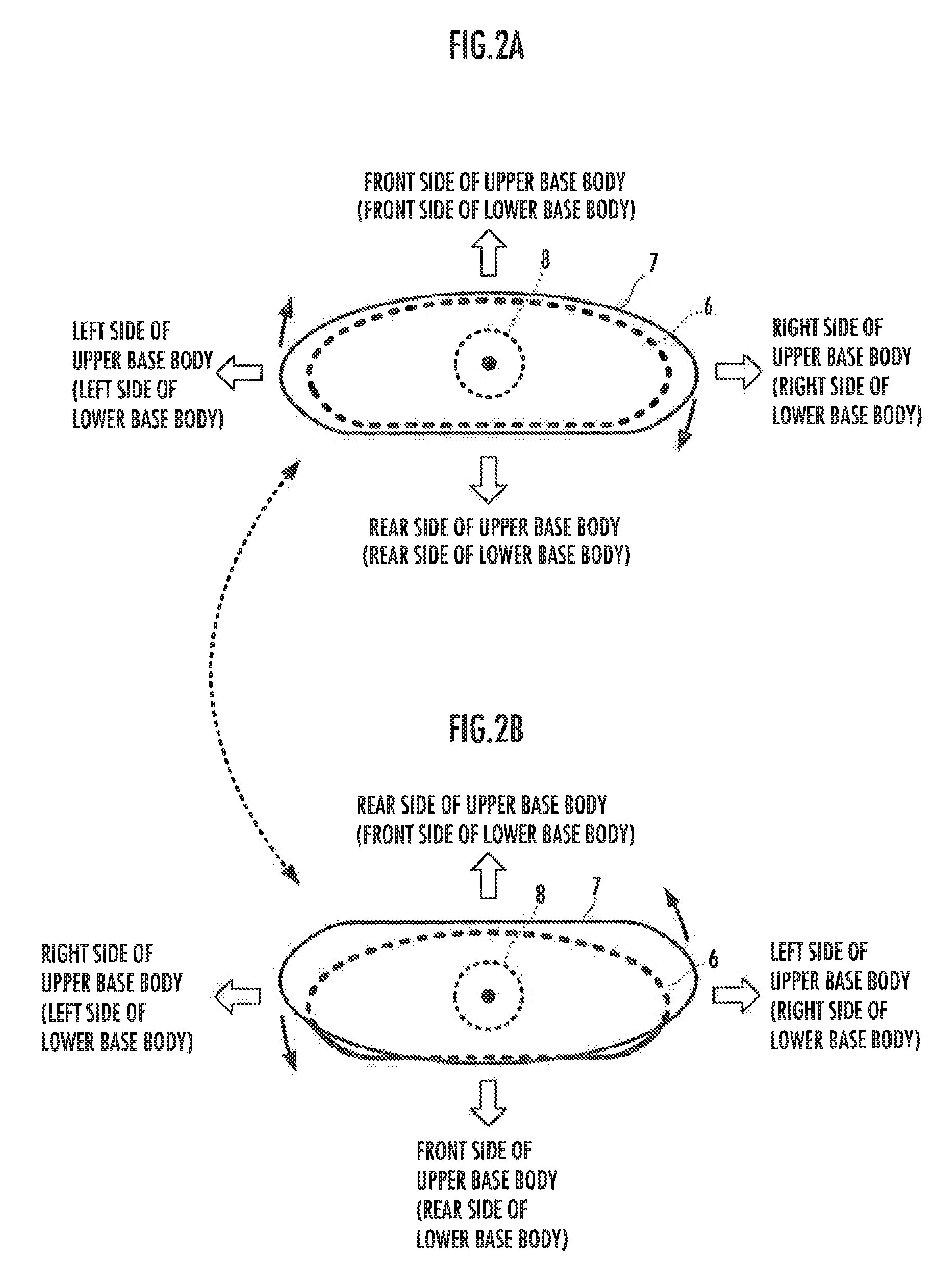
[0083]The base body assembly 2 is comprised of a lower base body 6 constituting the lower part of the base body assembly 2, an upper ...


PUM


Abstract

A mobile robot 1 has a lower base body 6 and an upper base body 7, which is relatively rotatable with respect to the lower base body 6. The robot 1 is configured to be capable of performing a travel motion in which the robot 1 travels in a state wherein the front side of the upper base body 7 is oriented to face the same direction as the front side of the lower base body 6, and a travel motion in which the robot 1 travels in a state wherein the front side of the upper base body 7 is oriented to face the same direction as the rear side of the lower base body 6. The middle portion of each of leg links 3 can be bended toward either the front side or the rear side of the lower base body 6.

Description

BACKGROUND OF THE INVENTION[0001]1. Field of the Invention[0002]The present invention relates to a mobile robot having a plurality of movable links extended from a base body.[0003]2. Description of the Related Art[0004]As a mobile robot having a plurality of movable links extended from a base body thereof, there has conventionally been known in general a humanoid robot provided with two leg links and two arm links as movable links, as described in, for example, Japanese Patent No. 3555107 (hereinafter referred to as “Patent Document 1”).[0005]This type of a mobile robot is configured such that the distal end parts of the movable links are moved with respect to the base body by the motions of the joints provided between the distal end portions of the movable links and the base body.[0006]Further, when traveling on a level ground or the like, the mobile robot usually travels in the direction of the front side of the base body thereof while observing the conditions in an external world...

Claims


Application Information

Patent Timeline
Patent Type & Authority Applications(United States)
IPC IPC(8): B25J5/00B25J9/16
CPCB25J5/00Y10S901/01B25J9/1694B62D57/032
Inventor KANEKO, HIROYUKIWATABE, TOMOKI
Owner HONDA MOTOR CO LTD
Why Eureka
Try Eureka