
Autonomous mobile device

a mobile device and autonomous technology, applied in the direction of distance measurement, electric programme control, programme control, etc., can solve the problems of large burden on the user, high time and effort (work, man-hours) required to create the environmental map, and the possibility of displaced setting points in comparison to their actual positions, so as to achieve less burden, more accurate autonomous travel, and high reliability

Active Publication Date: 2014-11-25
MURATA MASCH LTD
View PDF27 Cites 9 Cited by
  • Summary
  • Abstract
  • Description
  • Claims
  • Application Information

AI Technical Summary

Benefits of technology

This approach enables the creation of highly reliable environmental maps with reduced user burden, accurate autonomous travel, and flexibility in handling layout changes by updating maps dynamically and preventing errors from affecting the overall map accuracy.

Problems solved by technology

H10-143243, there is considerable burden on the user for setting the landmarks and performing other operations, and much time and effort (work, man-hours) are required to create the environmental map.
Meanwhile, in the method of creating the environmental map by using SLAM, for example, when attempting to set setting points (for instance, starting point, target pass-through point, goal point) on an environmental map which was prepared in advance, there is a possibility that such setting points will be displaced in comparison to their actual positions.
Moreover, the following problems have been indicated in the method of creating an environmental map by using SLAM.
1. There are cases where an inconsistency arises in the created environmental map due to the accumulation of measurement errors.
2. When the layout of the mobile area is partially changed, it is necessary to recreate the entire environmental map.

Method used


Image

  • Autonomous mobile device
  • Autonomous mobile device
  • Autonomous mobile device

Examples


first preferred embodiment

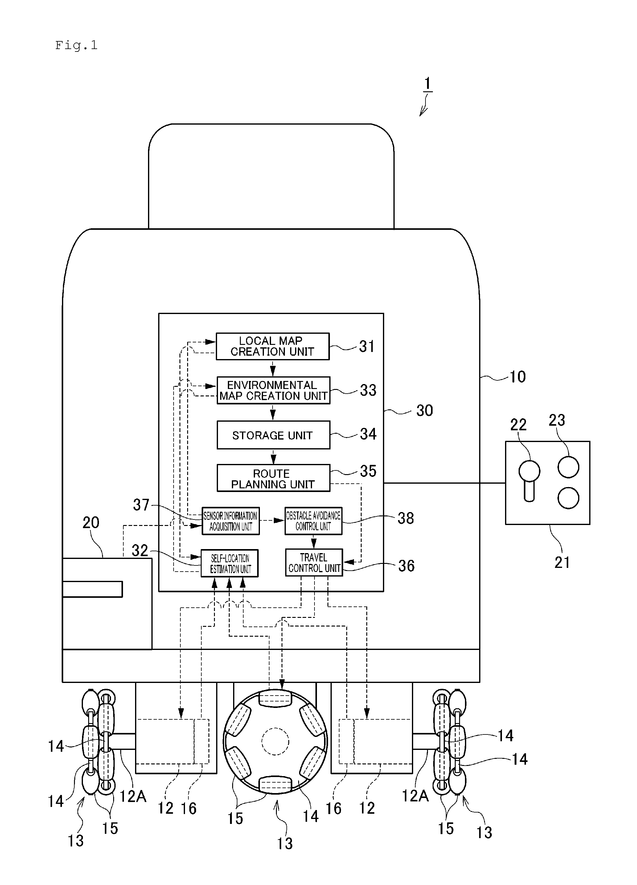
[0050]The configuration of an autonomous mobile device 1 according to the first preferred embodiment is foremost explained with reference to FIG. 1. FIG. 1 is a block diagram showing the configuration of the autonomous mobile device 1.

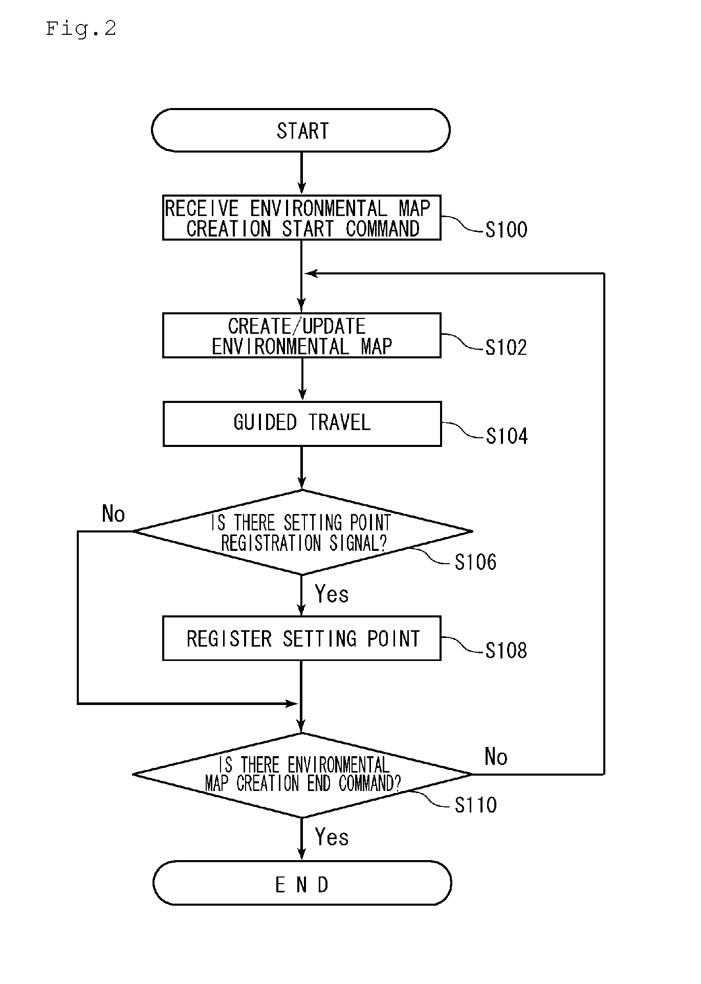
[0051]The autonomous mobile device 1 has a function of creating an environmental map (grid map showing an area with obstacles and an area without obstacles) of the travel space (area) by using SLAM when the autonomous mobile device 1 is being guided according to the user's remote operation, and, upon being guided and reaching a predetermined setting point, registering the actual self-location at such time as the position coordinate of a setting point on the environmental map (the mode for executing this function is referred to as the “installation mode”). Moreover, the autonomous mobile device 1 has a function of planning the travel route using the setting point on the environmental map that was created and stored, and autonomously traveling from the s...

second preferred embodiment

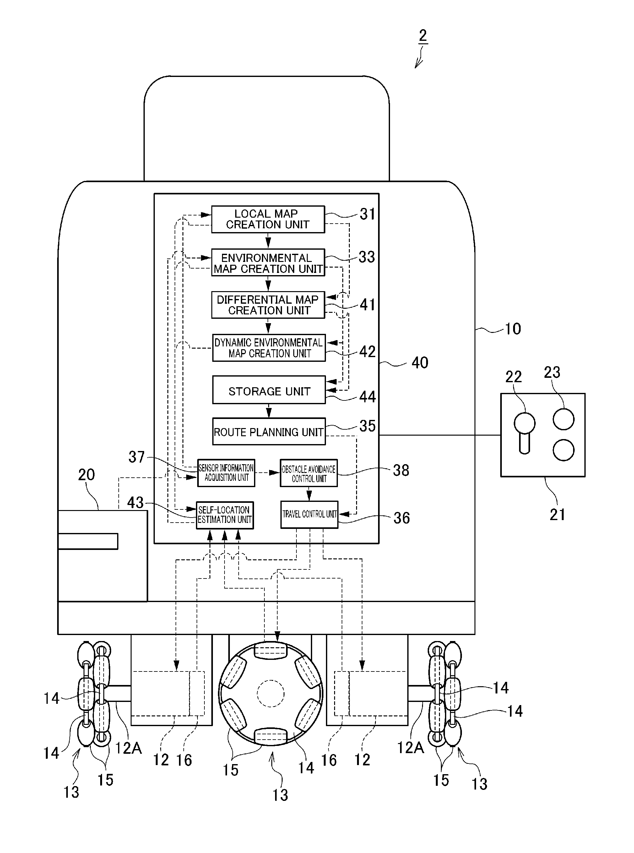
[0078]The configuration of the autonomous mobile device 2 according to the second preferred embodiment is now explained with reference to FIG. 4. FIG. 4 is a block diagram showing the configuration of the autonomous mobile device 2. Note that, in FIG. 4, elements which are the same as or equivalent to those of the first preferred embodiment are given the same reference numeral.

[0079]The autonomous mobile device 2 differs from the autonomous mobile device 1 in that it includes an electronic controller 40 as substitute for the electronic controller 30 described above. The electronic controller 40 differs from the electronic controller 30 in that it additionally includes a differential map creation unit 41 and a dynamic environmental map creation unit 42, and includes a self-location estimation unit 43 and a storage unit 44 as substitute for the self-location estimation unit 32 and the storage unit 34. These components which are different from the autonomous mobile device 1 are now exp...

third preferred embodiment

[0094]The configuration of the autonomous mobile device 3 according to the third preferred embodiment is now explained with reference to FIG. 6. FIG. 6 is a block diagram showing the configuration of the autonomous mobile device 3.

[0095]The autonomous mobile device 3 has an environmental map creation function of creating an environmental map including a plurality of partial maps, a route planning function of planning a travel route across a plurality of partial maps, and an autonomous travel function of moving along the travel route across a plurality of partial maps. More specifically, the autonomous mobile device 3 has a function of creating a plurality of partial maps configuring the environmental map (grid map showing an area with obstacles and an area without obstacles) of the mobile area by using SLAM when the autonomous mobile device 3 is being guided according to the user's remote operation, and, upon being guided and reaching a connecting point between the partial maps (her...


PUM


Abstract

An electronic controller defining an autonomous mobile device includes a self-location estimation unit to estimate a self-location based on a local map that is created according to distance / angle information relative to an object in the vicinity and the travel distance of an omni wheel, an environmental map creation unit to create an environmental map of a mobile area based on the self-location and the local map during the guided travel with using a joystick, a registration switch to register the self-location of the autonomous mobile device as the position coordinate of the setting point when the autonomous mobile device reaches a predetermined setting point during the guided travel, a storage unit to store the environmental map and the setting point, a route planning unit to plan the travel route by using the setting point on the environmental map stored in the storage unit, and a travel control unit to control the autonomous mobile device to autonomously travel along the travel route.

Description

BACKGROUND OF THE INVENTION[0001]1. Field of the Invention[0002]The present invention relates to an autonomous mobile device which plans a travel route and autonomously travels along the travel route.[0003]2. Description of the Related Art[0004]A conventional autonomous mobile device autonomously travels in an ambient environment. In order for an autonomous mobile device to autonomously travel in the ambient environment, an environmental map showing an area with objects (obstacles) and an area without objects within the travel space is required. Various methods have been proposed as the method of acquiring this kind of environmental map. Here, Japanese Patent Application Laid-open No. H10-143243 discloses technology for representing the ambient environment as a map using a landmark. With this technology, for example, if a mobile area is an office, the landmark is set at positions where the autonomous mobile robot is able to pass through such as corners and branching points of a hall...

Claims


Application Information

Patent Timeline
Patent Type & Authority Patents(United States)
IPC IPC(8): G05B19/18G06F17/00G05B15/00G05B19/00G05D1/00G05B19/04G01C22/00G05D1/02G05D3/00
CPCG05D1/0088G05D1/0272G05D1/024G05D1/0274G05D1/02G01C21/3804
Inventor TANAKA, SHOJINAKANO, TSUYOSHI
Owner MURATA MASCH LTD
Learn More