
Safety system and method for a coking facility

a safety system and coking facility technology, applied in the field of coke drums, to achieve the effect of minimizing the exposure of personnel and increasing safety

Inactive Publication Date: 2006-09-26
TERWISSCHA RICK +1
View PDF11 Cites 9 Cited by
  • Summary
  • Abstract
  • Description
  • Claims
  • Application Information

AI Technical Summary

Benefits of technology

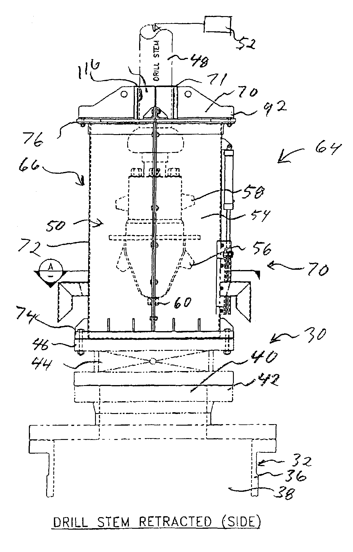
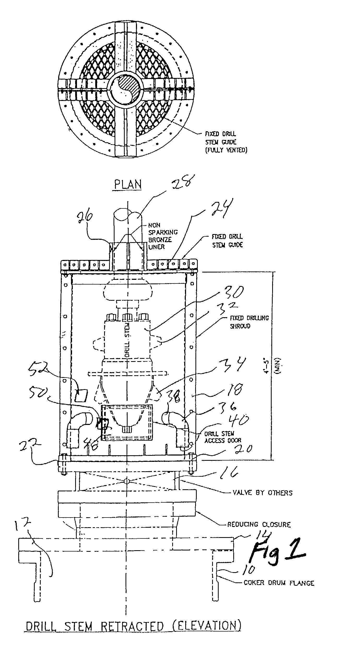
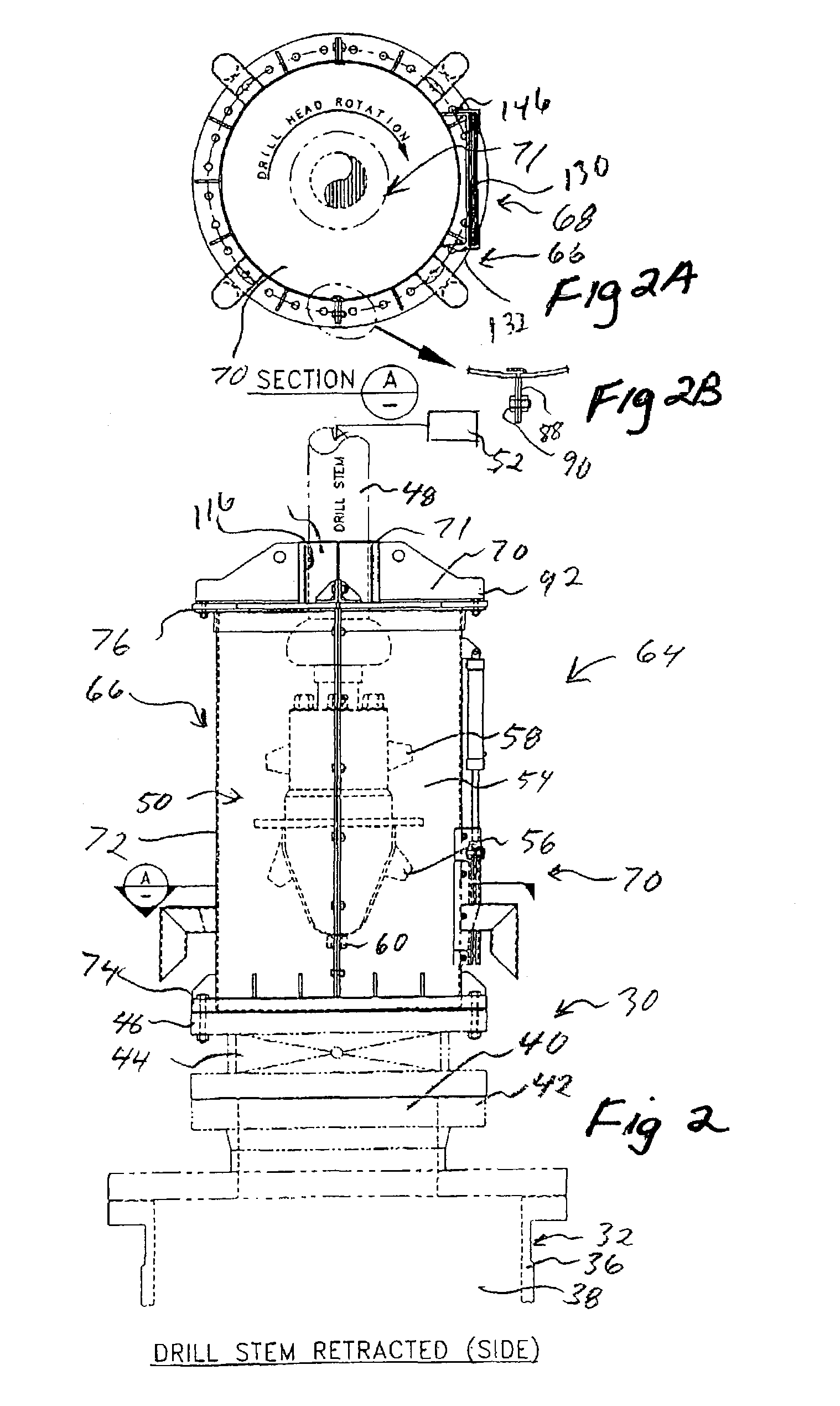
[0009]The system of the present invention is particularly adapted for use in a coking facility for the purpose of increasing safety and minimizing exposure of personnel. More particularly, the system of the present invention is used in that portion of the coking facility where there is at least one coke drums and also a drill assembly. The coke drum has an upper end opening defined by a surrounding opening structure of the coke drum. The drill assembly comprises a drill stem, a drill head at a lower portion of the drill stem, and a liquid discharge system. The liquid discharge system provides high pressure liquid for a liquid discharge section thereof at the drill head.
[0013]In a preferred form, there is a guide section location relative to the enclosing structure so as to be above the drill head with the drill head in its retracted position. The guide section has a through opening to accommodate the drill stem and is arranged to center the drill stem so that the drill head properly travels into and from the coke drum. The guide section in one preferred form, comprises a brass bushing which engages the drill stem and prevents unwanted sparking. Also, in a preferred form, the guide section is arranged to limit upward travel of the drill head outside of a region within the enclosing structure.
[0014]In this preferred embodiment, there is a door interlock system which is responsive to the door being in its open or closed position. This door interlock system has an operative connection to the liquid discharge system so as to be able to prevent flow of high pressure liquid form the discharge section at the drill head, in a manner that when the door is in the open position, jet liquid discharge from the discharge section at the drill head is prevented. In one preferred form, there is a door interlock control valve in the liquid discharge system, and the door interlock system operates to close the door interlock control valve when the door is in the open position.
[0015]Also, in a preferred form, there is a drill head interlock system which is responsive to location of the drill head and has an operative connection to the liquid discharge section. The drill head position interlock system is arranged so that when the drill head is moved out of its operating position within the drum, the liquid discharge system is prevented from discharging liquid through the discharge section at the drill head. In a specific embodiment shown herein, the head portion interlock system has a head portion interlock control valve to prevent flow from the liquid discharge section at the drill head. The door interlock control valve and the drill head position interlock control valve are in series so that when either of the interlock systems are operative to close its control valve, flow of the jet discharge to the discharge section at the drill head is prevented.
[0016]Further, in the preferred embodiment, there is a venting system to cause cooling air to enter a region defined by the enclosing structure, and to flow from the region defined by the venting structure to have a cooling effect within the enclosed structure. In a specific embodiment shown herein, the venting system comprises an inlet air section to enable air to enter into a lower portion of the region defined by the enclosing structure, and an air outlet section to enable flow in the region defined by the enclosing structure to flow outwardly from the enclosed structure.

Problems solved by technology

Obviously, there are any number of connecting devices which could be used, and since these are all well known to people of ordinary skill in this art, these will not be itemized.

Method used


Image

  • Safety system and method for a coking facility
  • Safety system and method for a coking facility
  • Safety system and method for a coking facility

Examples


Embodiment Construction

[0034]It is believed that a better understanding of various features of the present invention will be obtained by first describing a prior art coking drum and drill assembly, such as shown in U.S. Pat. No. 5,022,799, and then describing more specifically the prior art components which are utilized in the safety system of the present invention, with these being followed by a description of the newly added features of the combination in the present invention.

[0035]Reference is first made to FIG. 1, which is labeled Prior Art, and which is the first page of the drawings shown in U.S. Pat. No. 5, 022,799 (Torres et al.) issued Jun. 11, 1991. There is shown a coke drum 1 having an upper lid 2 and a lower lid 3. At the lower portion of the feed inlet 4 connected to a feed line 5, and these are to transfer the heaviest portion of the crude oil (commonly referred to as “residual oil”) into the coke drum 1. At the top end of the drum 1, is an aperture 6 with a flange 7 surrounding the apertu...


PUM

PropertyMeasurementUnit
pressureaaaaaaaaaa
volatileaaaaaaaaaa
temperatureaaaaaaaaaa

Abstract

A safety system for a coking facility where there is a coke drum and a drill assembly. When the coke accumulates in the drum, a drill head of the drill assembly is lowered into the coke drum to emit high pressure water jets to remove the coke from the coke drum. There is a enclosing structure with an access door which is fixedly mounted at a location above an upper opening of the coke drum, so that when the drill head is moved out of the coke drum and there is an accidental jet water discharge, it will be redirected at a location within the enclosing structure. Interlock systems are provided.

Description

RELATED APPLICATIONS[0001]This application claims priority benefit of U.S. Ser. No. 60 / 356,991, filed Feb. 12, 2002.BACKGROUND OF THE INVENTION[0002]a) Field of the Invention[0003]The present invention relates generally to coke drums, and more particularly to an apparatus which is used in connection with a drill assembly that is used in the coking drums for removing the coke from the coke drum.[0004]b) Background Art[0005]Coke is commonly made in a petroleum processing facility as follows. The petroleum product goes through a fractionating process where some of the more volatile material is extracted, and the petroleum product that remains is a heavy, more viscous petroleum product which is at about 720° degrees F. when it leaves the fractionator. This is passed through a heater which raises the temperature of the petroleum product to about 930° degrees F., and this petroleum product is directed through a switch valve alternatively into one or the other of two coke drums. When the p...

Claims


Application Information

Patent Timeline
Patent Type & Authority Patents(United States)
IPC IPC(8): C10B43/00
CPCC10B41/06C10B33/006
Inventor TERWISSCHA, RICKMAAKAD, GUY
Owner TERWISSCHA RICK
Learn More