
Sealing structure and fluid treatment unit

a technology of sealing structure and fluid treatment unit, which is applied in the direction of filtration separation, separation process, and treatment involving filtration, can solve the problems of shortening the service life of the device, difficulty in operation, and inconvenience in operation, so as to facilitate operation and reduce friction, the effect of avoiding abrasion of the sealing member

Inactive Publication Date: 2016-04-07
CHAU YIU CHAU
View PDF3 Cites 4 Cited by
  • Summary
  • Abstract
  • Description
  • Claims
  • Application Information

AI Technical Summary

Benefits of technology

The present invention provides a fluid treatment device with a sealing structure that reduces wear and tear on the device, while also allowing for easier operation and a better treatment effect. By designing the valve core to be smaller and providing a guide plate to direct the water flow, the device can improve treatment efficiency without increasing its size. The invention also includes a low friction sealing cover that moves in parallel relative to the support cover, which eliminates abrasion between the two components. Overall, the device provides a better user experience and a more effective treatment.

Problems solved by technology

The valve plate has a larger section (close to that of the housing) and is in close contact with a sealing member in the valve compartment, and thus a force required for rotating the valve plate is relatively larger, thereby being inconvenient in operation.
In addition, in the case of often rotating the valve plate with a large angle, the friction between the valve plate and the sealing member easily leads to degradation of sealing therebetween, thereby shortening a service life of the device.
During the mounting process, the sealing member is rotated with the base, thereby generating a very large frictional resistance, which on one hand, causes difficulties in operation, and on the other hand, makes the sealing member be vulnerable to injuries so as to destroy the sealing effect.
Additionally, as the demand for fluid treatment is enhanced, treatment paths of a treatment unit in the prior art fail to provide support for the demand, so the treatment unit itself also needs to be improved.

Method used


Image

  • Sealing structure and fluid treatment unit
  • Sealing structure and fluid treatment unit
  • Sealing structure and fluid treatment unit

Examples


Embodiment Construction

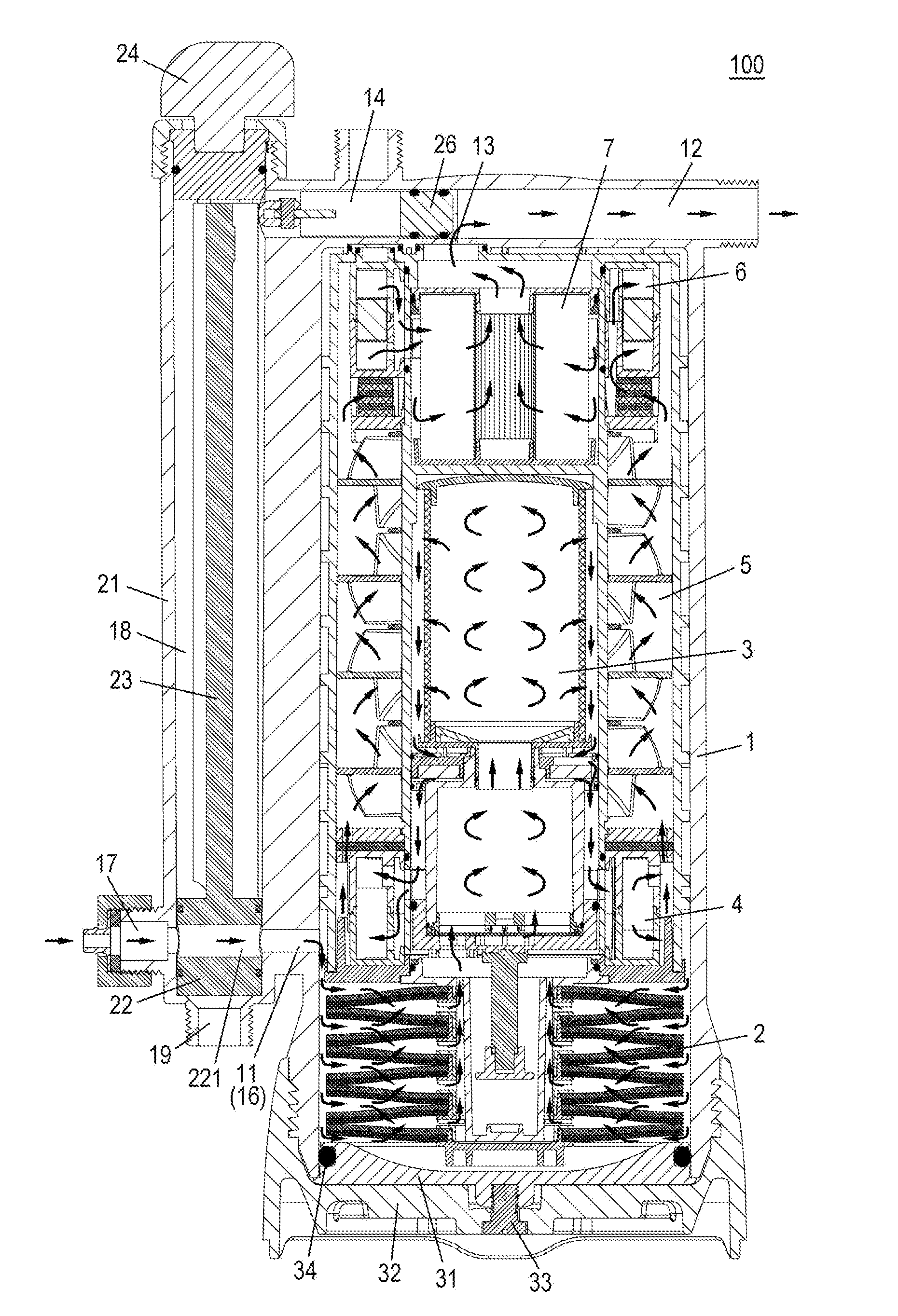
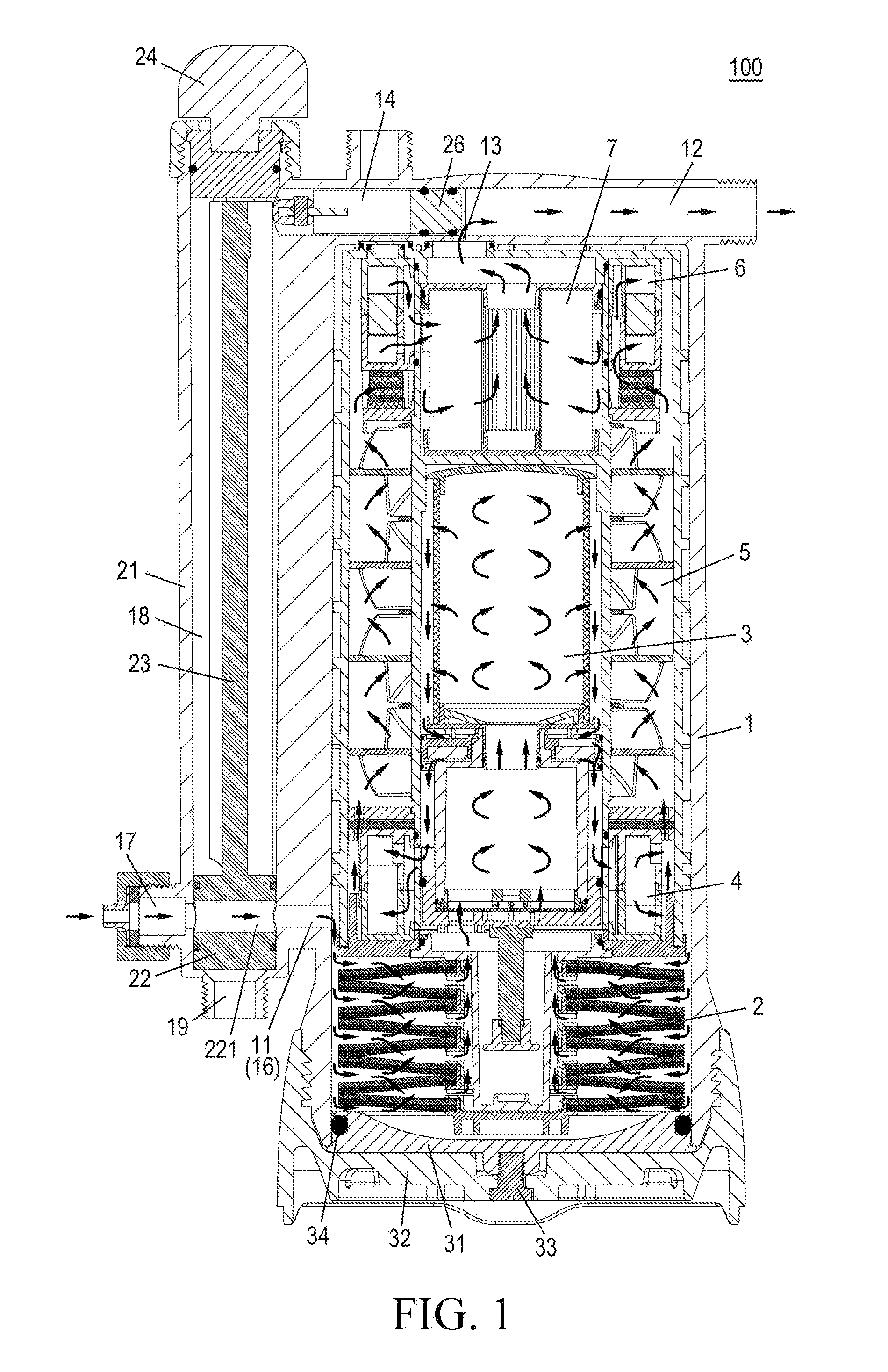
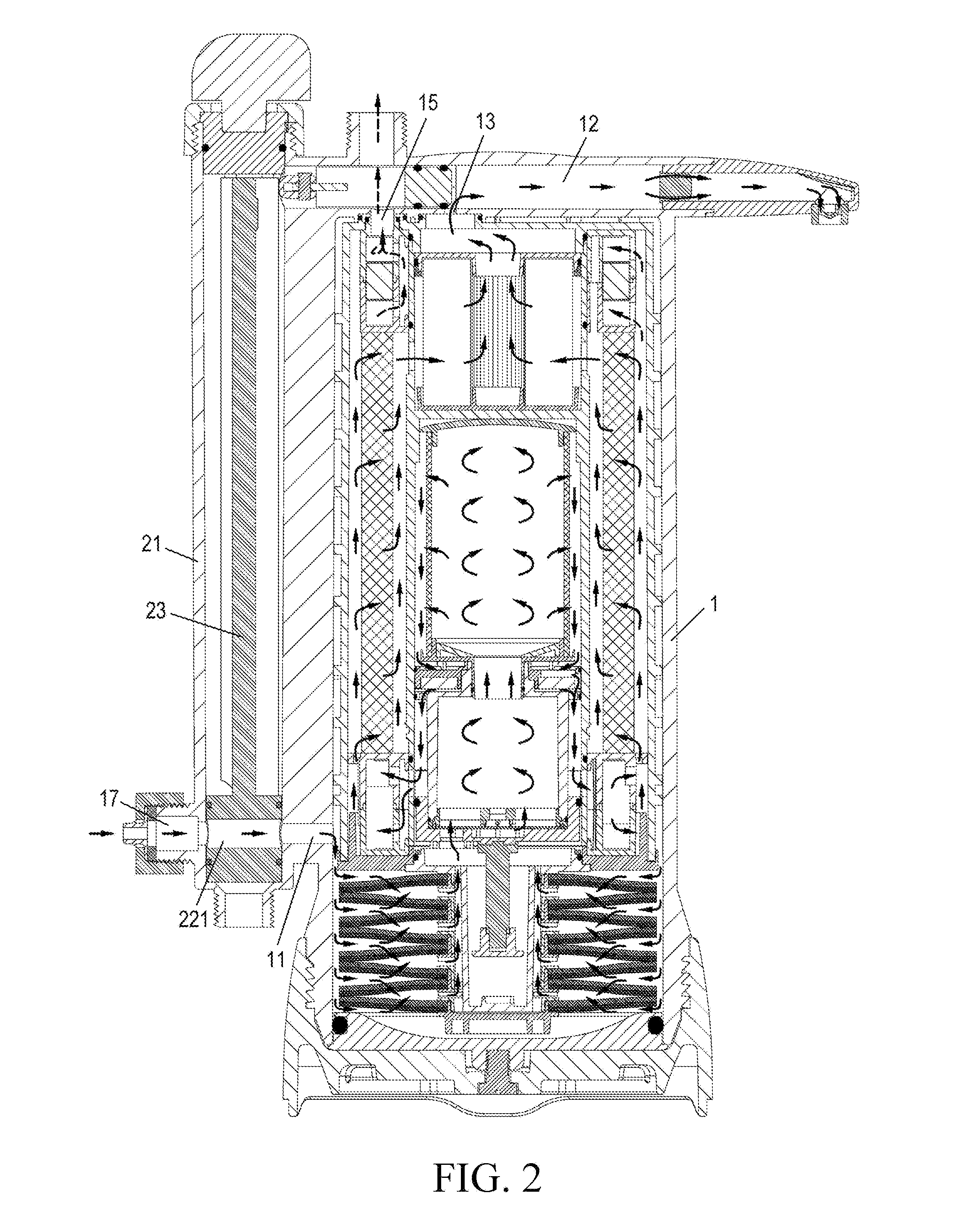
[0035]Referring to above explanations, it can be known that the fluid treatment device and respective treatment units and mechanisms including the same can be used for, but not exclusively, water treatment. It is used for water treatment in its optimized use. For the convenience of expression, a water treatment device, a water treatment unit, a water treatment medium and the like are taken as examples hereinafter to introduce the present invention. It should be appreciated that the water herein may be any fluid.

[0036]FIG. 1 is a schematic sectional view of the water treatment device according to a first embodiment of the present invention, and the device is in a normal treatment state of treating water to be treated. In preferable applications, the treatment device 100 may be an apparatus connected with a tap for treating city or other drinking water sources. Such water treatment device at least can work under a normal treatment state of treating the water to be treated, and a backw...


PUM

PropertyMeasurementUnit
inclined angleaaaaaaaaaa
distanceaaaaaaaaaa
heightaaaaaaaaaa

Abstract

A fluid treatment unit and a sealing structure which is preferably for the fluid treatment unit are provided. The sealing structure includes: a cylinder with an opening formed at one end thereof, the cylinder comprising an inner wall surface and an outer wall surface, and an outer thread being provided on the outer wall surface; a sealing cover which is capable of hermetically cooperating with the inner wall surface of the cylinder to seal the opening; a support cover which is capable of being connected with the cylinder by thread engagement; when the support cover and the cylinder are relatively rotated in order to achieve a threaded connection of the support cover and the cylinder, the support cover is capable of supporting the sealing cover and impelling it to move in parallel so as to allow the sealing cover to reach a position at which it seals the opening.

Description

RELATED APPLICATIONS[0001]This patent arises from a divisional of U.S. application Ser. No. 13 / 582,647, which is a national stage application of International PCT Application No. PCT / CN2011 / 071518, filed on Mar. 4, 2011, and is hereby incorporated herein by reference in its entirety. Further, this patent claims priority to Chinese Patent Application 201010129273.8, which was filed on Mar. 5, 2010 and is hereby incorporated herein by reference in its entirety.FIELD OF THE INVENTION[0002]The present invention relates to a fluid treatment device, and particularly to a fluid treatment unit, a sealing structure and a manual switching mechanism employed by this fluid treatment device.BACKGROUND OF THE INVENTION[0003]A fluid treatment device generally uses one or several fluid treatment mediums to treat various fluids, such as water and so on, and generally contains one or more fluid treatment units accommodating the fluid treatment mediums. When fluid passes through a fluid treatment medi...

Claims


Application Information

Patent Timeline
Patent Type & Authority Applications(United States)
IPC IPC(8): C02F1/42B01D24/46B01D15/10B01D24/16
CPCC02F1/42B01D24/167B01D24/4631C02F2201/002C02F2301/04C02F2303/16B01D15/10B01D29/21B01D29/41B01D29/58B01D29/668C02F1/003C02F2201/004B01D35/30B01D24/10B01D29/117B01D29/925B01D2201/304
Inventor CHAU, YIU CHAU
Owner CHAU YIU CHAU
Learn More