Automatic door child safety lock release in a crash event

a technology of automatic release and child safety, which is applied in the direction of passenger lock actuation, electrical locking circuit, instruments, etc., can solve the problems of child locks producing potentially dangerous situations, potentially opening rescue persons, and children or any occupants of the rear seats cannot be removed from the vehicle, so as to prevent miscommunication

Active Publication Date: 2016-04-07
CONTINENTAL AUTOMOTIVE SYST INC
View PDF0 Cites 10 Cited by
  • Summary
  • Abstract
  • Description
  • Claims
  • Application Information

AI Technical Summary

Benefits of technology

[0010]Various other data is transmitted along with the signals from the vehicle ECU provide different functionality. A rolling counter is employed in order to ensure consistent transmission of data from the ECUs. General data on the operation of the ECUs is transmitted concerning the operating parameters of the ECU such as, but not limited to, voltages, temperatures, and number of transmissions by the ECUs. This data can be interpreted in order to provide optimal operation by the ECU. Checksum protection is transmitted in order to verify the entire signal has been sent from the vehicle ECU to the child safety lock ECU and prevent miscommunication between the ECUs. An ECU identification signal is employed in order to establish the identity of the ECU which is currently transmitting.

Problems solved by technology

While this acts to protect the child or other occupant during normal operation of the vehicle, the child locks can produce a potentially dangerous situation.
For example, if there is an accident and the vehicle catches on fire, the child or any occupant from the rear seat cannot be removed from the vehicle by opening the door from the inside or outside unless the door is unlocked from a different location like a key fob or door unlock switch near front seats.
In the case of a rollover accident or other accident, the passenger cannot exit nor potentially can a rescue person open the rear door for removal of the occupant.

Method used


Image

  • Automatic door child safety lock release in a crash event
  • Automatic door child safety lock release in a crash event
  • Automatic door child safety lock release in a crash event

Examples


Embodiment Construction

[0020]The following description of the preferred embodiment(s) is merely exemplary in nature and is in no way intended to limit the invention, its application, or uses.

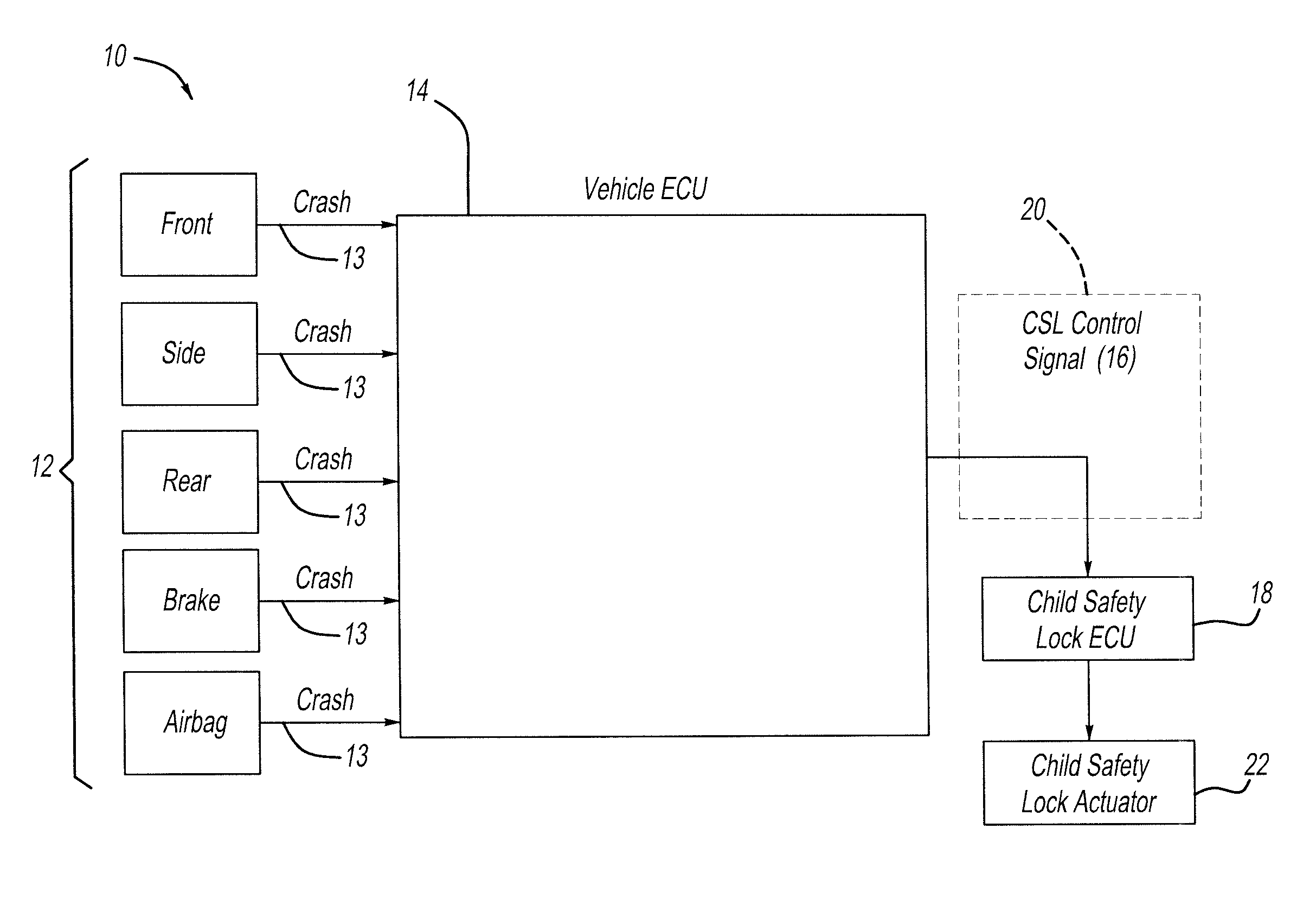
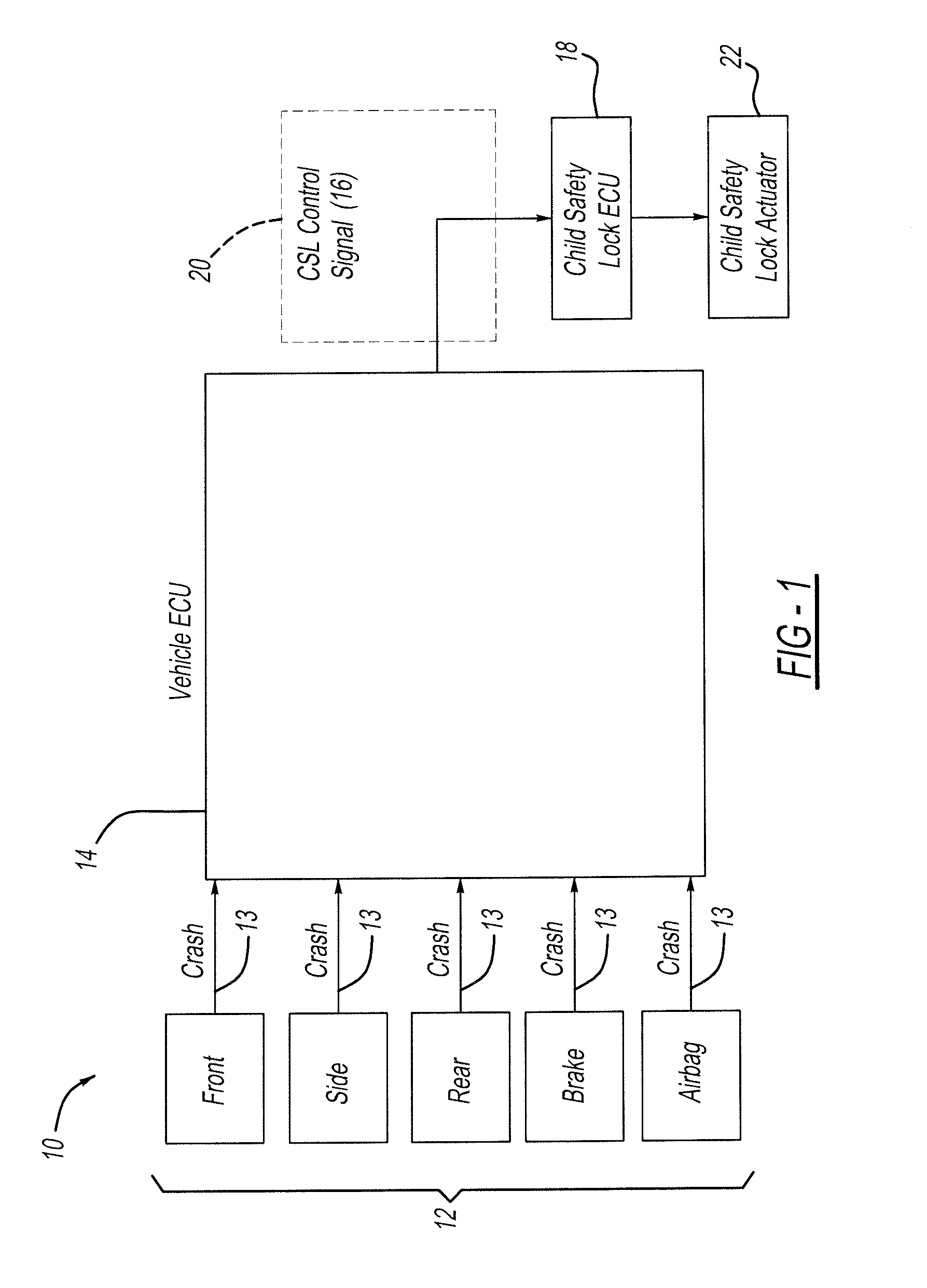
[0021]Referring now to the Figures, with particular reference to FIG. 1, a schematic diagram of an automated child safety unlocking system 10 is shown. The child safety unlocking system 10 uses two or more crash sensors 12 that are each configured to generate a crash signal upon detection of an event. The two or more crash sensors 12 are located at various portions on a vehicle body. The crash sensors 12 can include pressure sensors, accelerometers, light sensors, or virtually any other type of sensor capable of sensing or detecting an event such as a vehicle collision with an object or other vehicle. Depending upon the number of crash sensors 12 that generate a crash signal 13, the child safety unlocking system can be configured to determine the severity of a vehicle impact using the information or crash signal or th...


PUM


Abstract

An automated child safety unlocking system for automobiles which disengages the child safety locks and unlocks the doors at appropriate times during events such as vehicle crashes. The vehicle ECU continually monitors the status of the vehicle to check if a crash event has occurred via various methods such as the status of airbag deployment, accelerometers placed in the car, and crumple points. In the event of a crash the vehicle ECU transmits one of at least two CSL command signals a child safety lock ECU. The command signals are each specific to an event severity and event type, and the child safety lock ECU then interprets the signal and acts according to the signal type. If the data interpreted indicates a crash, the child safety lock ECU unlocks the child safety locks, and if it does not determine a crash has not occurred, the locks remain engaged.

Description

CROSS-REFERENCE TO RELATED APPLICATIONS[0001]This application claims the benefit of U.S. Provisional Application No. 62 / 059,519 filed Oct. 3, 2014.FIELD OF THE INVENTION[0002]The present invention is related to an automatic child safety lock release during an accident.BACKGROUND OF THE INVENTION[0003]“Child safety locks” are present on most vehicles. In particular, vehicles with a back seat have a manual release in the outer portion of the door which is exposed by opening of the door. Typically, there is a recessed switch in the door that is actuated by a screwdriver, or key, or by hand, and switched manually from an open position where the locks function in a normal manner, or a locked position where the exposed locks in a rear door cannot be manually manipulated by a rear seat occupant.[0004]The purpose for this type of lock is to avoid undesired opening by a child or other rear seat occupant of the rear door which might place the child or occupant at risk. Additionally, the door ...

Claims


Application Information

Patent Timeline
Patent Type & Authority Applications(United States)
IPC IPC(8): E05B77/26E05B77/54E05B81/58E05B77/02
CPCE05B77/26E05B81/58E05B77/54E05B77/02E05B77/12
Inventor FERNANDEZ-AGUILERA, DAVIDCARLOS-GONZALEZ, ARTURO
Owner CONTINENTAL AUTOMOTIVE SYST INC
Why Eureka
Try Eureka