Interior aircraft light unit and method of producing an interior aircraft light unit

a technology for aircraft and light units, applied in aircraft indicators, advertising, lighting and heating apparatus, etc., can solve the problems of insufficient reliability of approaches, inconvenient production, and inconvenient use of approaches, and achieve high power rating, high light intensity, and high efficiency of light sources

Active Publication Date: 2016-04-07
GOODRICH LIGHTING SYST
View PDF2 Cites 1 Cited by
  • Summary
  • Abstract
  • Description
  • Claims
  • Application Information

AI Technical Summary

Benefits of technology

[0021]According to a further embodiment, the at least one light source is one light source or two light sources or three light sources. In other words, the interior aircraft light unit may comprise exactly one light source or exactly two light sources or exactly three light sources. Due to the shading of certain regions of the source side light intensity distribution via the semi-transparent layer, the light source(s) can be operated at a high power rating, emitting high amount(s) of light. In this way, such a low number of light sources, such as one, two or three light sources, may be sufficient for achieving the desired overall light yield.
[0022]According to a further embodiment, the at least one light source is at least one LED. In other words, each of the at least one light source is an LED. LEDs are generally highly efficient light sources, having a large light yield per electric power. By means of the transparency distribution of the semi-transparent layer, the high directivity of the LEDs may be evened out, such that a very even adjusted light intensity distribution may be achieved without the need of complicated optical structures and / or without the need of running the LEDs below their efficient high power ratings.
[0023]According to a further embodiment, the semi-transparent layer is a film layer. In this way, the semi-transparent layer does not add much to the dimensions of the interior aircraft light unit. Such a film layer structure is a very space-efficient means of achieving the evening out of the source side light intensity distribution.

Problems solved by technology

In order to satisfy such limit values, prior art approaches have employed very complicated optical structures, commonly employing a large number of light sources.
Such approaches have proven to be not satisfactory with respect to their reliability.
Also, their production has been found to be too complicated and cumbersome.
However, due to measuring inaccuracies, a limited resolution for measuring and inverting, a limited number of transparency levels, and a limited resolution on the semi-transparent layer, providing the plurality of transparency values within + / −50% of the inverse of the corresponding source side light intensity value is sufficient for providing a very even adjusted light intensity distribution.

Method used


Image

  • Interior aircraft light unit and method of producing an interior aircraft light unit
  • Interior aircraft light unit and method of producing an interior aircraft light unit
  • Interior aircraft light unit and method of producing an interior aircraft light unit

Examples


Embodiment Construction

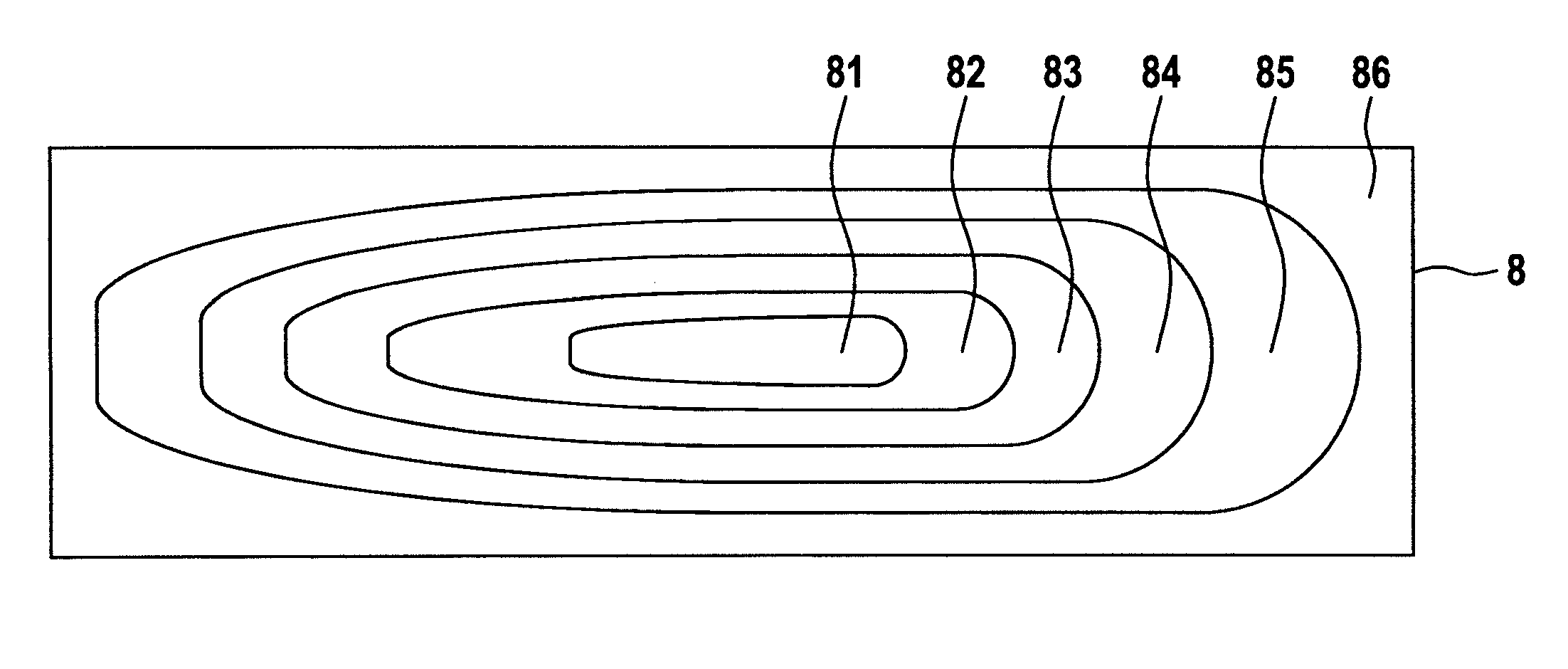
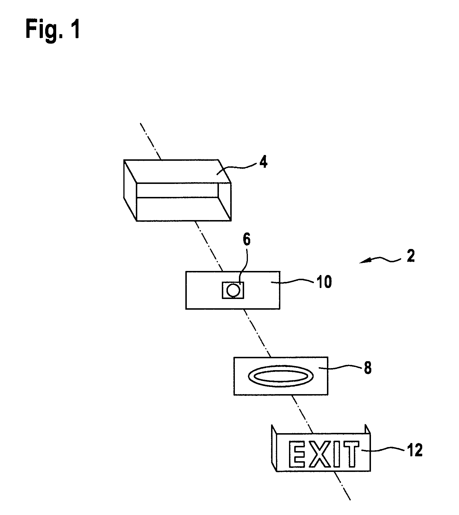
[0039]FIG. 1 shows an interior aircraft light unit 2 in accordance with an exemplary embodiment of the invention. The interior aircraft light unit 2 is shown in an exploded view, such that the individual elements can be seen better.

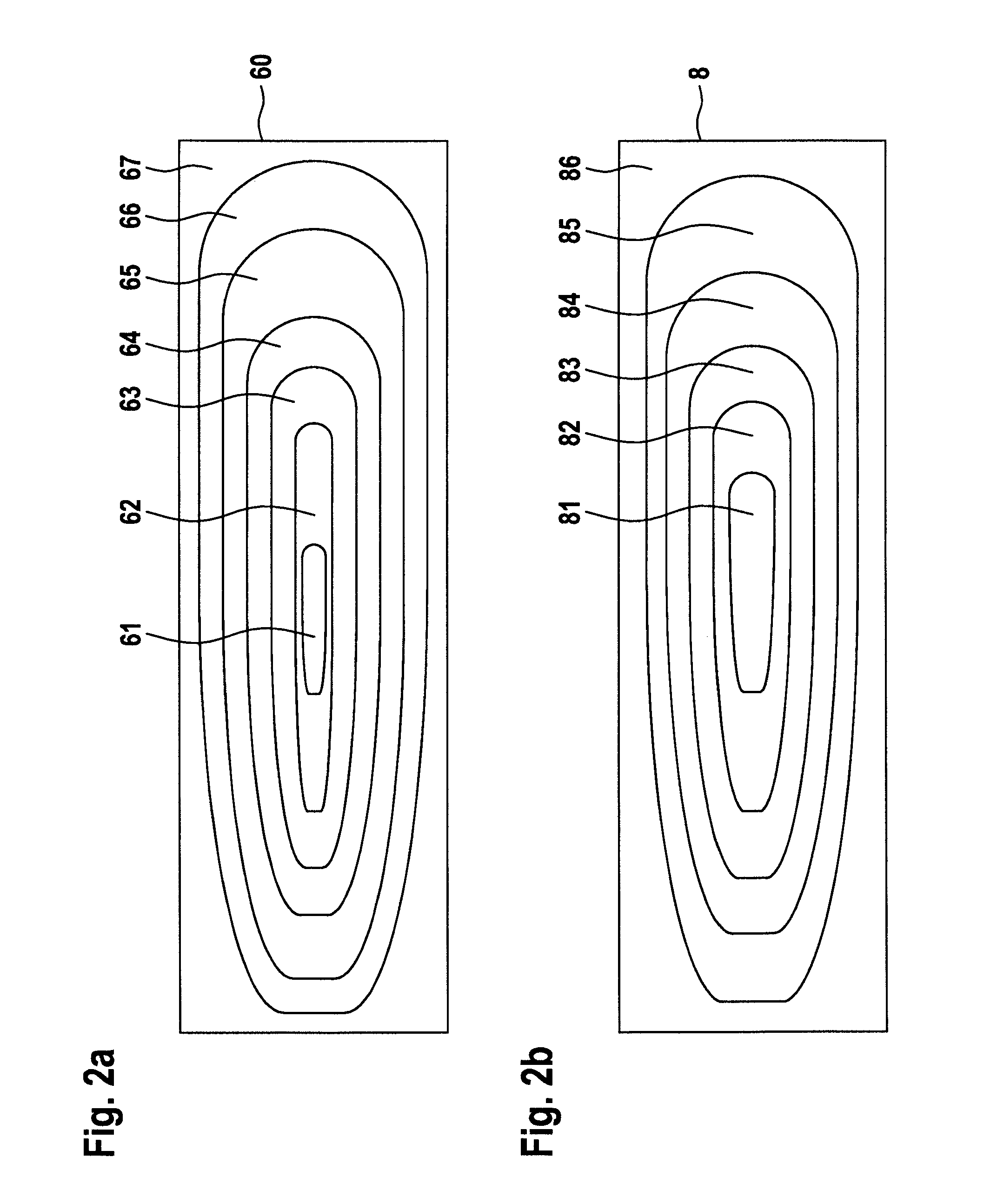
[0040]The interior aircraft light unit 2 comprises a housing 4, a mounting plate 10, to which an LED 6 is mounted, a semi-transparent layer 8, and a lens cover 12. The housing 4 is a generally cuboid structure in the exemplary embodiment of FIG. 1. The mounting plate 10 has a generally planar front surface, and the LED 6 is mounted to substantially the middle of the mounting plate 10. When assembled, the mounting plate 10 is positioned towards the back of the housing 4.

[0041]The lens cover 12 has a generally flat front portion and two side portions, with which the lens cover 12 is clipped onto the housing 4 during the assembly. The lens cover 12 is made of a generally transparent, white material, with the word exit being formed in red letters. During the ...


PUM

PropertyMeasurementUnit
transparencyaaaaaaaaaa
power consumptionaaaaaaaaaa

Abstract

An interior aircraft light unit includes at least one light source, in operation emitting light with a source side light intensity distribution, the source side light intensity distribution having a first intensity region and a second intensity region, with the first intensity region having a higher light intensity than the second intensity region, and a semi-transparent layer, disposed between the at least one light source and an outside of the interior aircraft light unit, for transforming the source side light intensity distribution into an adjusted light intensity distribution, wherein the semi-transparent layer has a transparency distribution having a lower degree of transparency in the first intensity region than in the second intensity region, such that the adjusted light intensity distribution is closer to an even light intensity distribution than the source side light intensity distribution.

Description

FOREIGN PRIORITY[0001]This application claims priority to European Patent Application No. 14187536.9 filed Oct. 2, 2014, the entire contents of which is incorporated herein by reference.TECHNICAL FIELD[0002]The present invention relates to interior aircraft lighting. In particular, it relates to interior signal lights, such as exit signs.BACKGROUND OF THE INVENTION[0003]For such exit signs, the Federal Aviation Regulations (FAR) require a fairly even light intensity distribution. In particular, the FAR set limit values for the ratio between the brightest portion of the exit sign and the least bright portion of the exit sign. An exemplary limit value for this ratio is 3. In order to satisfy such limit values, prior art approaches have employed very complicated optical structures, commonly employing a large number of light sources. Such approaches have proven to be not satisfactory with respect to their reliability. Also, their production has been found to be too complicated and cumbe...

Claims


Application Information

Patent Timeline
Patent Type & Authority Applications(United States)
IPC IPC(8): F21S8/10
CPCF21S48/00F21Y2101/02F21W2101/08F21W2101/06B64D45/00B64D2045/007F21Y2115/10F21W2106/00F21W2107/30G08B7/062G09F13/0409G09F13/10G09F21/06G09F2013/1813G09F2013/05
Inventor SCHOEN, CHRISTIANBECKER, STEFANSCHALLENBERG, BJORN
Owner GOODRICH LIGHTING SYST
Why Eureka
Try Eureka