Wave energy absorption device, a power take-off assembly and a wave energy system

Inactive Publication Date: 2017-04-13
OCEAN HARVESTING TECH
View PDF9 Cites 9 Cited by
  • Summary
  • Abstract
  • Description
  • Claims
  • Application Information

AI Technical Summary

Benefits of technology

[0035]In a preferred embodiment, the force applied to the elongated means in each buoy connected to the power take-off and gen

Problems solved by technology

Due to its proportional characteristics of the damping force to the velocity, passive loading gives very high peak forces in relation to the average power extracted from the wave, and the damping force profile is not optimal to capture the most power out of each wave.
This is a challenge for the component sizing and efficiency of the power take-off system.
But it is often difficult to control the damping force when adding energy storag

Method used


Image

  • Wave energy absorption device, a power take-off assembly and a wave energy system
  • Wave energy absorption device, a power take-off assembly and a wave energy system
  • Wave energy absorption device, a power take-off assembly and a wave energy system

Examples


Example

[0054]In the following, a detailed description of a wave energy system according to the invention, including an oscillation device for improved power capture and efficiency in combination with energy storage in the power take-off, and a plurality of wave energy absorption devices connected to a common hub according to the invention, will be described in detail.

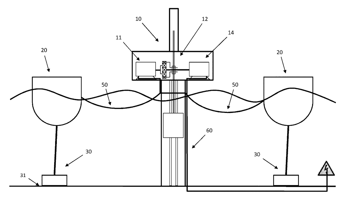
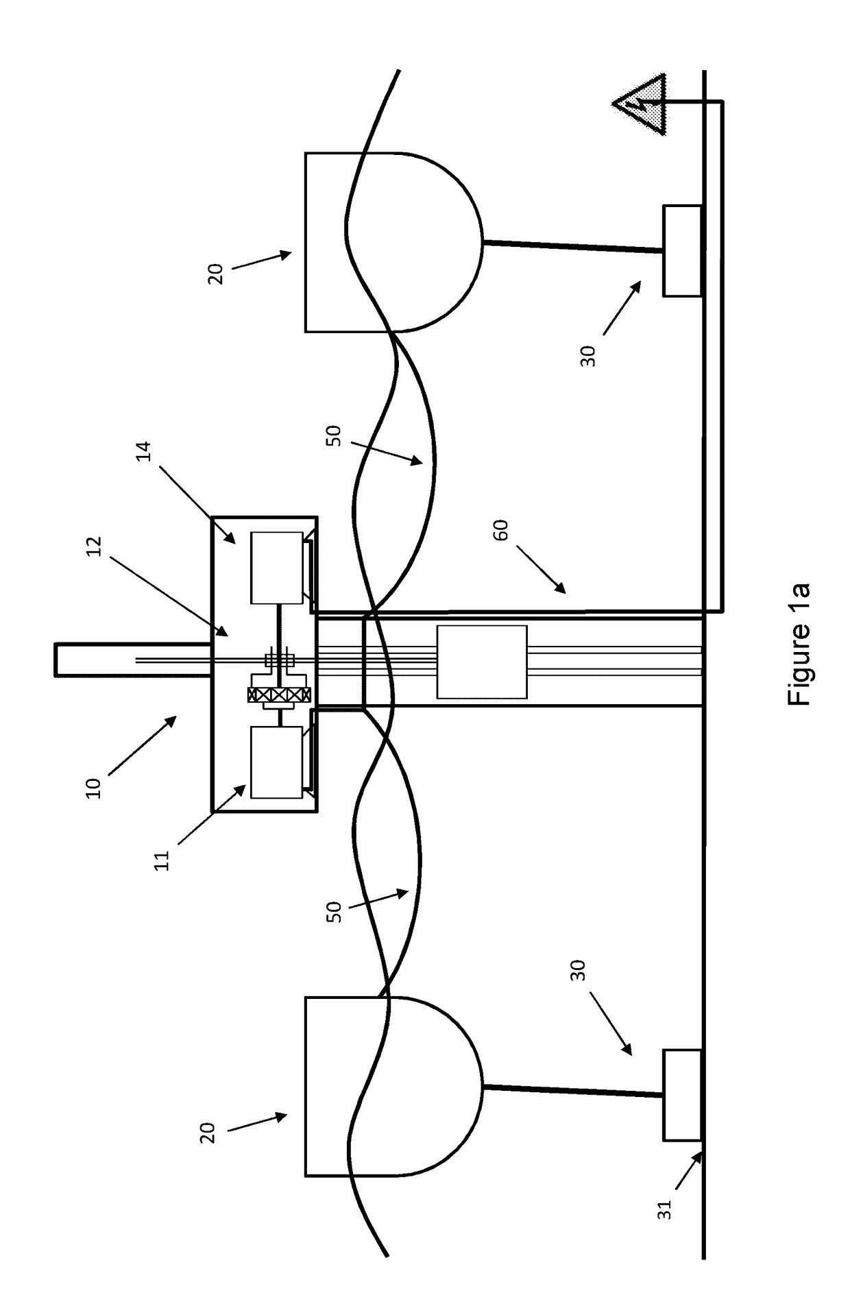
[0055]FIG. 1a is a schematic view of a wave energy system with two buoys 20 attached via flexible hydraulic hoses 50 to a power take-off and generator assembly in the form of a hub 10. Each buoy is moored to the seabed with a mooring rope 30 to the sea bed 31. The hub comprises a hydraulic motor 11, an energy storage device in the form of a gravity storage device 12 and a hydraulic generator 14, which exports electric power through cable 60.

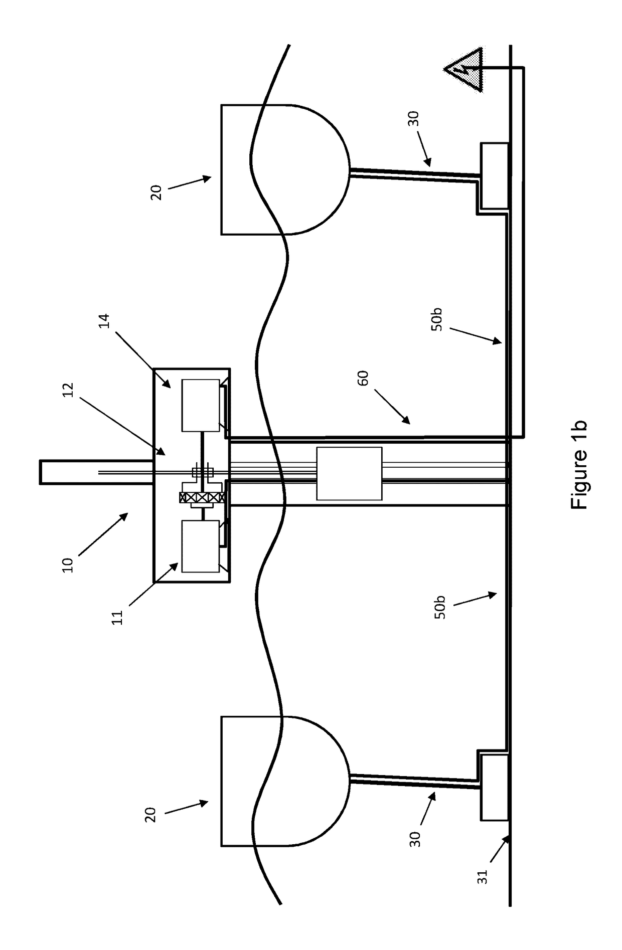
[0056]FIG. 1b is a similar schematic view as FIG. 1a but with buoys connecting to a fixed piping system 50b on the sea floor 31 to transfer high pressure hydraulic fluid to the hub 10. A fi...


PUM


Abstract

A wave energy absorption device comprises a buoy adapted to move with movements of water, and a buoy oscillation device attached to the buoy, the buoy oscillation device comprising an elongated means and a rotary means adapted to interact with the elongated means. A hydraulic pump with variable displacement is connected to the rotary means and connectable to a hydraulic circuit. When the buoy moves with movements of water, relative movement is created between the elongated means and the rotary means, whereby the hydraulic pump transforms kinetic energy into hydraulic energy which to the hydraulic hose, and whereby a torque is applied to the rotary means by the hydraulic pump to dampen or amplify the movements of the buoy. The buoy oscillation device provides individual control of the force applied to the buoy by change of displacement in the hydraulic pump.

Description

TECHNICAL FIELD[0001]The present invention relates generally to a wave energy absorption device, a power take-off and generator assembly comprising energy storage, a hydraulic collection system connecting a plurality of wave energy absorption units to a common power take-off and generator assembly, wherein the force applied to each wave energy absorption device can be independently controlled without significant interference from the energy storage.BACKGROUND ART[0002]Strategies for controlling the damping force applied to the buoy are widely studied with the purpose to increase the power capture for a wave energy converter. The optimal damping force to use depend greatly on the wave size. If the optimal damping force is not applied, the buoy will either be over or under dampened through the wave and will thus capture less power.[0003]The most commonly used control strategy is the so called passive loading, and this is often compared with reactive control considered to be the optima...

Claims


Application Information

Patent Timeline
IPC IPC(8): F03B13/14F15B21/14F15B15/08
CPCF03B13/14F15B15/08F15B21/14F05B2240/93F05B2260/406F05B2260/4031F05B2220/706F03B13/1845F04B17/02F03B13/186F05B2260/42Y02E10/30Y02P80/10E02B9/08F03B13/18
Inventor SIDENMARK, MIKAEL
Owner OCEAN HARVESTING TECH
Why Eureka
Try Eureka