Electrical connector and manufacturing method thereof

Active Publication Date: 2016-04-07
DONGGUAN JITS IND +1
View PDF5 Cites 26 Cited by
  • Summary
  • Abstract
  • Description
  • Claims
  • Application Information

AI Technical Summary

Benefits of technology

[0008]One objective of the present invention is to provide an electrical co

Problems solved by technology

This traditional USB connector has too many components and complex manufacturing process, thereby increasing the manufacturing cost.
Two rows of soldering pins will undoubtedly increase the size of the USB connector and take up more space.
The applic

Method used


Image

  • Electrical connector and manufacturing method thereof
  • Electrical connector and manufacturing method thereof
  • Electrical connector and manufacturing method thereof

Examples


Example

Embodiment 1

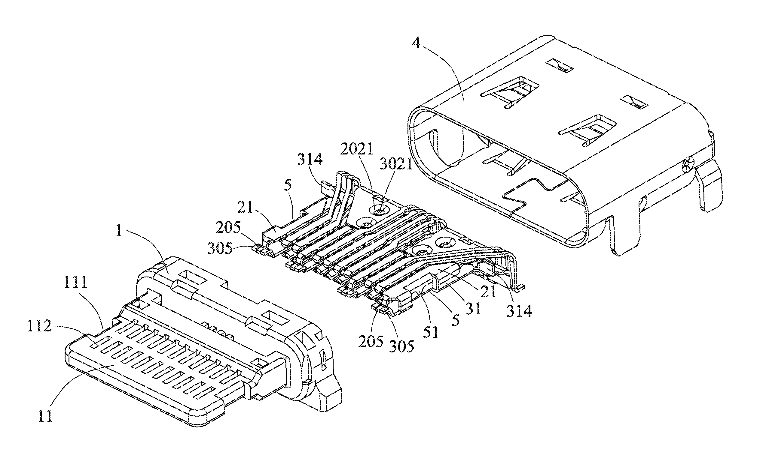
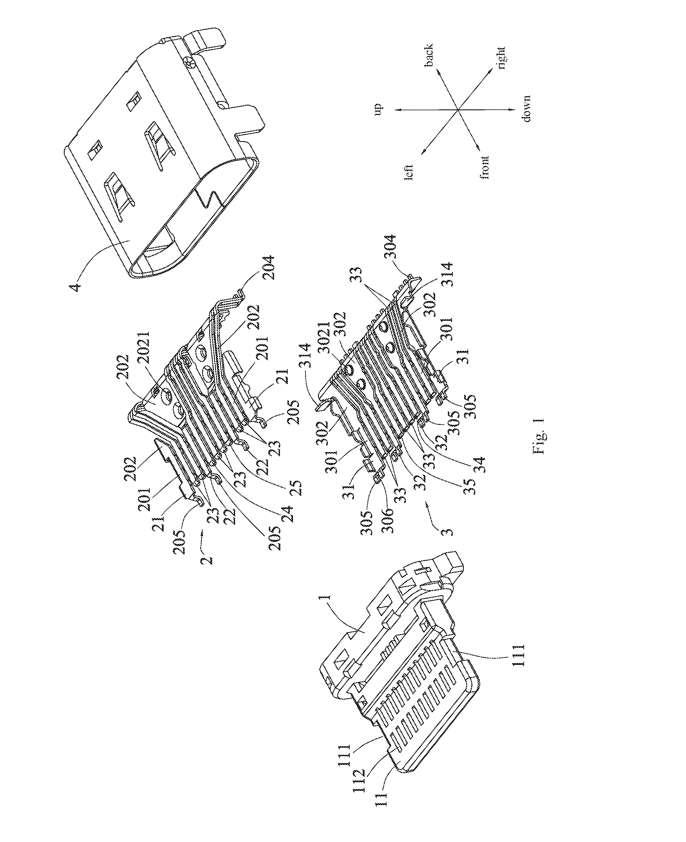
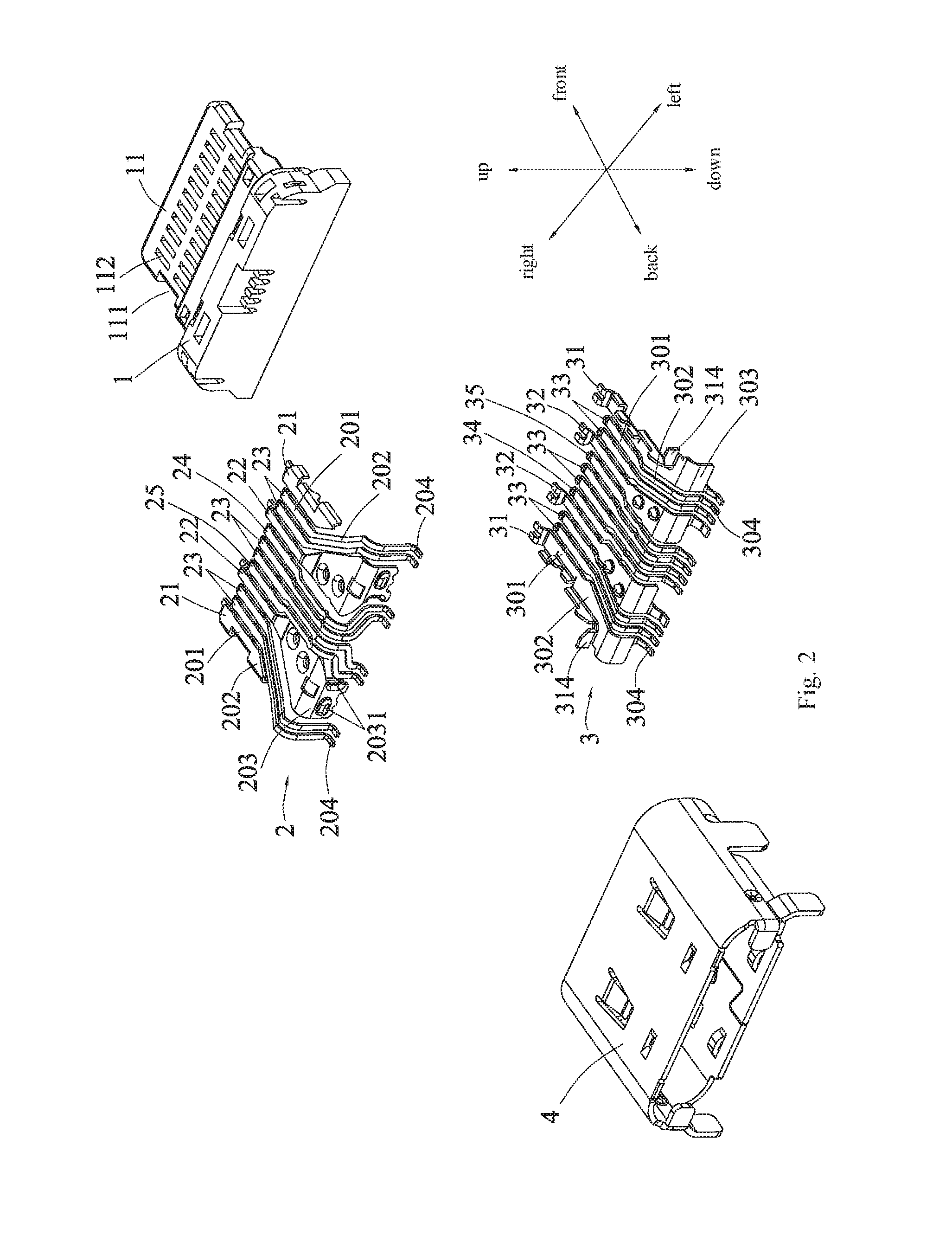
[0065]As shown in FIGS. 1 to 7, the present invention provides an electrical connector for being soldered with a circuit board (not shown), the electrical connector includes an insulating body 1, and an upper row of conductive terminals 2 and a lower row of conductive terminals 3 buried and molded in the insulating body 1. The upper row of conductive terminals 2 includes a plurality of upper conductive terminals, which are arranged in a row and located above, and the lower row of conductive terminals 3 includes a plurality of lower conductive terminals, which are arranged in a row and located below. The electrical connector further includes a metal housing 4, the metal housing 4 coats the insulating body 1.

[0066]The insulating body 1 has a tongue plate 11, each upper conductive terminal has an upper contact portion 201 and an upper fixing portion 202, the upper fixing portion 202 is buried in the insulating body 1, and the upper contact portion 201 is exposed on the uppe...

Example

Embodiment 2

[0089]Differences between embodiment 1 and embodiment 2 have: (1) the connecting method of the upper fixing portions 202 of the upper power terminals 22 and the lower fixing portions 302 of the lower power terminals 32; (2) the connecting method of the upper feeding strip 20 and the lower feeding strip 30 in the step three.

[0090]Referring to FIGS. 8 and 9, a recessed portion 207 is formed by recessing the upper fixing portion 202 of each upper power terminal downward, a bottom surface of the recessed portion 207 is contacted with a top surface of the lower fixing portion 302 of the lower power terminal 32, and a riveting hole 208 passing through the recessed portion 207 and the lower fixing portion 302 of the lower power terminal 32 is formed by riveting pressing. The upper fixing portion 202 of the upper power terminal 22 and the lower fixing portion 302 of the lower power terminal 32 can be fixedly connected by this riveting method, but the present invention is not so ...

Example

Embodiment 3

[0092]As shown in FIGS. 10 to 13, an isolating piece 312, a side shield 316, and a back shield 42 are provided in the present embodiment to further improve the performance of the electrical connector.

[0093]Specifically, as shown in FIGS. 10 and 11, two isolating pieces 312 are formed by respectively extending inward from the two external edges of the upper row of conductive terminals 2 or the lower row of conductive terminals 3 to the middle of the upper row of conductive terminals 2 and the lower row of conductive terminals 3, that is, the two isolating pieces 312 are formed by extending inward from the two external edges of the upper ground terminals 21 or the lower ground terminals 31, in the present embodiment, the two isolating pieces 312 are formed by respectively extending inward from the two external edges of the lower ground terminals 31 to the above of the adjacent pair of the lower differential signal terminals 33 so as to isolate the upper and lower different...


PUM

PropertyMeasurementUnit
Electrical conductoraaaaaaaaaa
Widthaaaaaaaaaa
Bending strengthaaaaaaaaaa

Abstract

A electrical connector includes an insulating body having a tongue plate, a plurality of upper conductive terminals having upper contact portions, and a plurality of lower conductive terminals having lower contact portions; the upper and lower conductive terminals are buried and molded in the insulating body, the upper contact portions and the lower contact portions are vertically aligned one by one and respectively exposed on an upper surface and a lower surface of the tongue plate; the upper conductive terminals vertically corresponding to the lower conductive terminals one by one so as to form a plurality of corresponding columns, and the upper and lower conductive terminals of at least one corresponding columns are fixedly connected with each other by riveting.

Description

RELATED APPLICATIONS[0001]This application claims the benefit of priority to Chinese Patent Application No. 201510498033.8, filed on Aug. 14, 2015, which is hereby incorporated by reference in its entirety.FIELD OF THE INVENTION[0002]The present invention relates in general to an electrical connector, and more particularly to an electrical connector having simple manufacture, small size, and high-speed transmission.BACKGROUND OF THE INVENTION[0003]Currently, USB (Universal Serial Bus) connectors have been widely used in various electronic products, such as data and charging interfaces of mobile phone and computer, and with the development of society, the electronic products require higher speed transmission for the USB connector.[0004]A Chinese patent (CN201420479369.0) discloses an USB connector that is capable of high-speed transmission, which includes a metal spacer, a first terminal group, a first plastic body in which the metal spacer and the first terminal group are integrally...

Claims


Application Information

Patent Timeline
IPC IPC(8): H01R13/6585H01R43/24B29C70/68B29C70/72H01R24/60H01R43/16
CPCH01R13/6585H01R24/60H01R43/16B29C70/683B29C70/72B29K2995/0005H01R2107/00B29L2031/3481B29K2105/20B29K2995/0007H01R43/24H01R13/5045H01R24/00
Inventor CHEN, HUANYI
Owner DONGGUAN JITS IND
Why Eureka
Try Eureka