Display device

a technology of a display device and a display screen, which is applied in the manufacture of final products, lighting and heating apparatus, and support devices, etc., can solve the problems of disturbing additional light phenomena, undesired and disturbing, etc., and achieve the effect of avoiding stray light or undesired light phenomena

Inactive Publication Date: 2016-04-07
E G O ELEKTRO GERAETEBAU GMBH
View PDF7 Cites 2 Cited by
  • Summary
  • Abstract
  • Description
  • Claims
  • Application Information

AI Technical Summary

Benefits of technology

[0006]The invention addresses the problem of providing a display device mentioned in the introduction with which problematic issues in the prior art are avoided and it is possible, in particular, to avoid stray light or undesired light phenomena.

Problems solved by technology

This can lead to undesired and disturbing additional light phenomena.

Method used


Image

  • Display device
  • Display device
  • Display device

Examples


Embodiment Construction

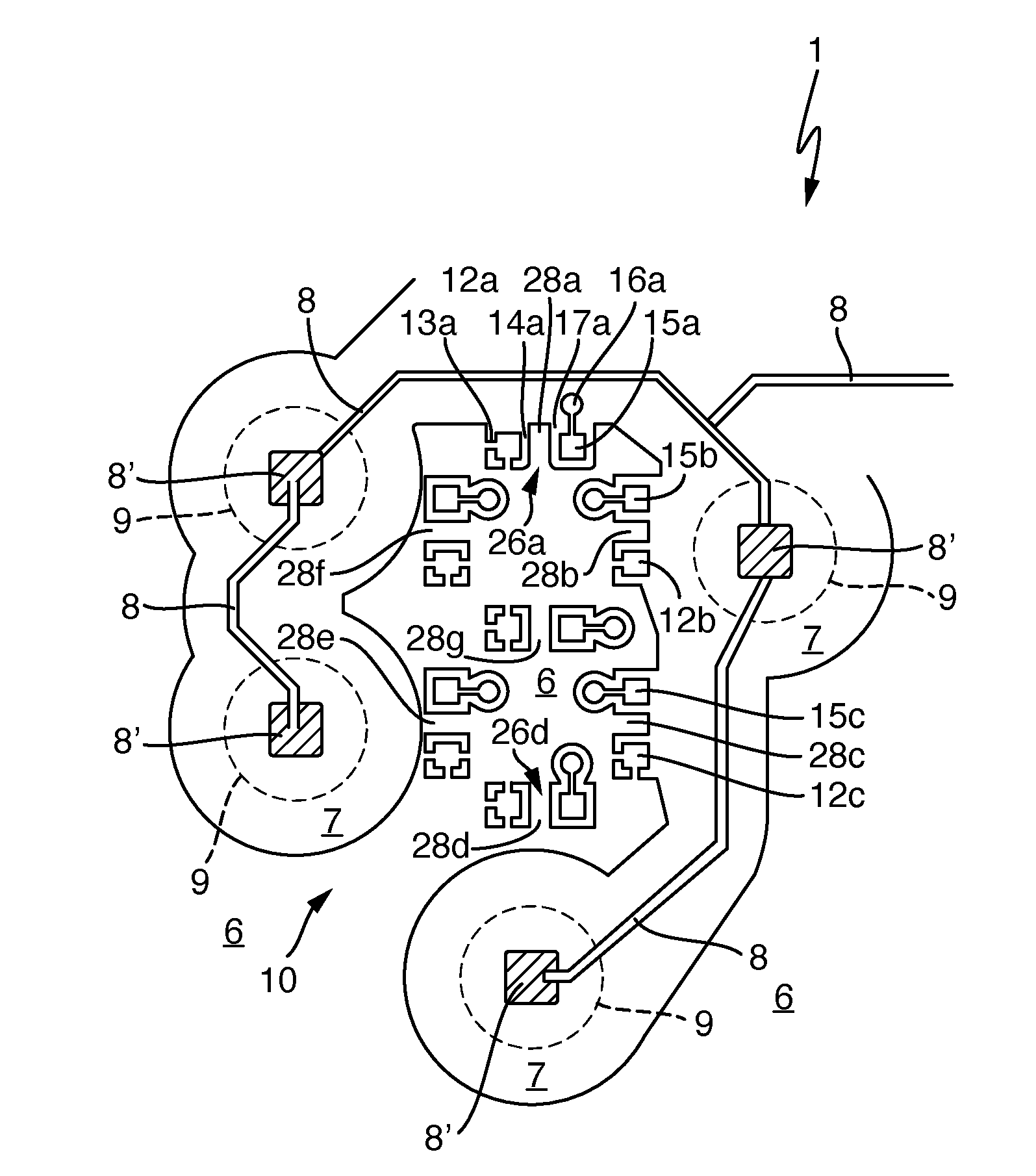
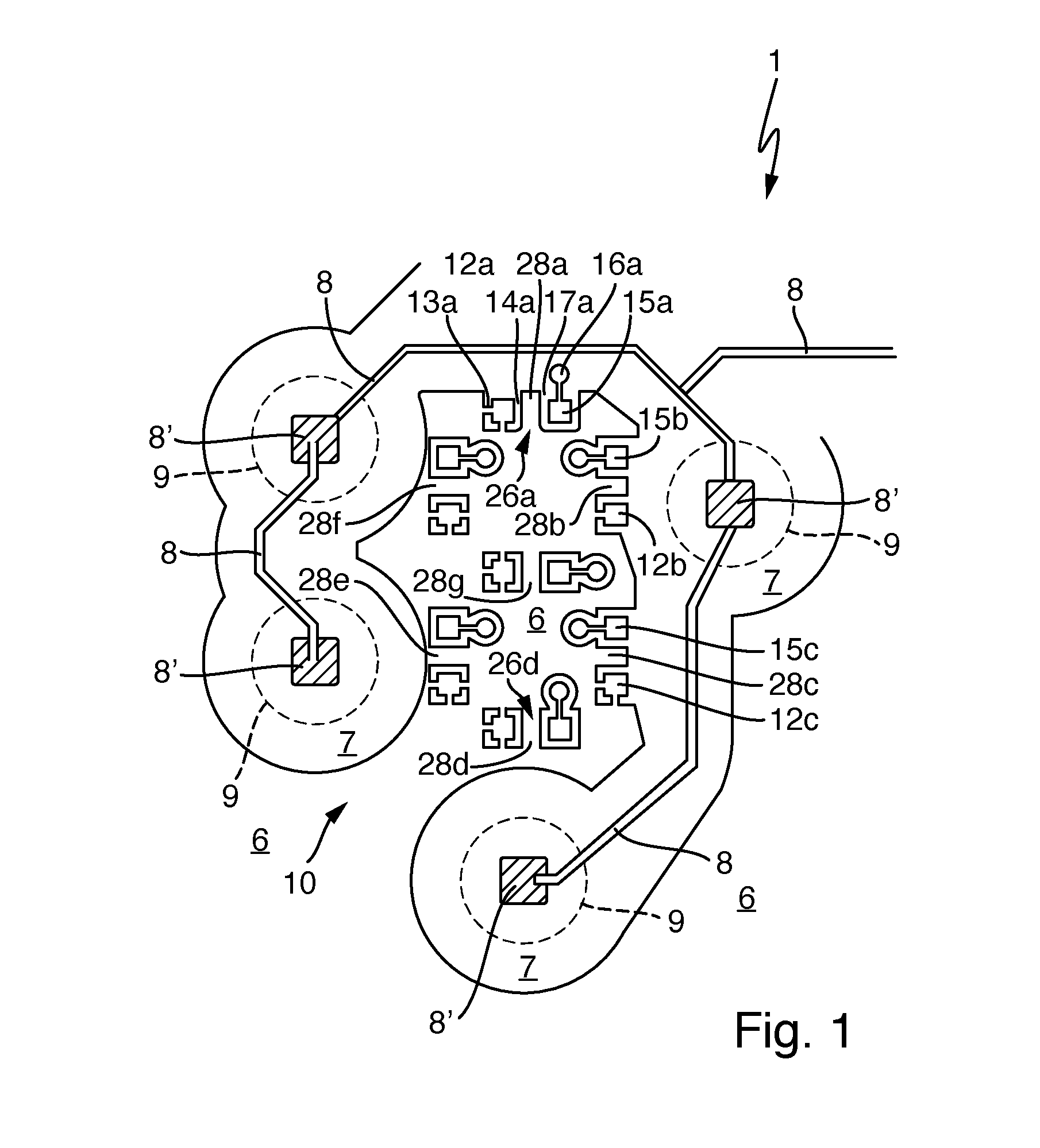
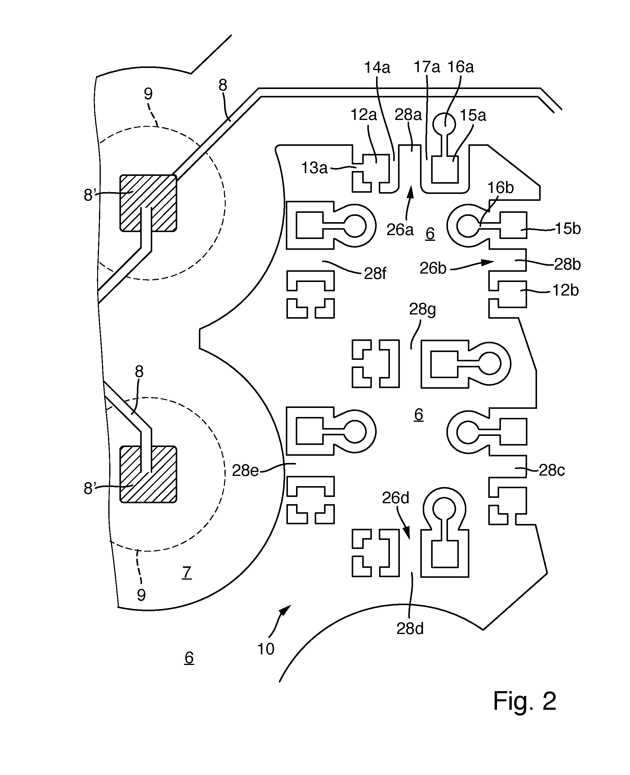
[0036]FIG. 1 shows schematically and FIG. 2 shows a central segment in an enlarged view of a display device 1 such as can be arranged in a hob below an operator interface, in particular the hob plate composed of glass ceramic. The display device 1 comprises a printed circuit board 5, which in the present case is formed from a material containing optical fibres. The printed circuit board has an upper copper coating 6 and a lower copper coating (not illustrated), as is known. A seven-segment display 10 is arranged on the printed circuit board 5. For electrically connecting the seven-segment display, structures or free regions 7 are worked, specifically usually etched, from the upper copper coating 6 and, if appropriate, also from the lower copper coating.

[0037]In addition, on the printed circuit board 5 of the display device 1, touch switches are also provided for a combined operating unit. For this purpose, relatively thin sensor conductor tracks 8a are provided, which pass to sensor...


PUM


Abstract

The invention relates to a display device including a printed circuit board and a number of light-emitting diodes, wherein a structured copper coating is provided on the printed circuit board. The copper coating has shielding regions which reduce or prevent penetration of light emitted downwards from the light-emitting diodes into the printed circuit board. This reduces or prevents emergence of light from the printed circuit board again at undesired locations.

Description

CROSS-REFERENCE TO RELATED APPLICATIONS[0001]This application claims priority to German Application No. 10 2014 220 188.8, filed Oct. 6, 2014, the contents of which are hereby incorporated herein in its entirety by reference.TECHNOLOGICAL FIELD[0002]The invention relates to a display device for a domestic appliance, in particular for a hob or an oven.BACKGROUND[0003]Such display devices are known from DE 102012219040 A1 or U.S. Pat. No. 5,917,165 A. They can be used for example for various domestic appliances such as hobs, ovens or microwave appliances. The light-emitting diodes are often arranged such that they jointly form a seven-segment display. In order that information communicated to a user by the display device via the light-emitting diodes can readily be read and, furthermore, a design that is aesthetically appealing to a certain extent is also achieved, it is advantageous if, as far as possible, light emitted by the light-emitting diodes is only emitted in a defined direct...

Claims


Application Information

Patent Timeline
Patent Type & Authority Applications(United States)
IPC IPC(8): H05K1/02H05K1/09F21V23/00H05K1/18
CPCH05K1/0274H05K1/181H05K1/09F21Y2101/02F21V23/00H05K2201/10106H05K1/0296H05K1/111H05K2201/09227H05K2201/09363H05K2201/10128H05K2201/2054Y02P70/50
Inventor HENRICH, MICHA
Owner E G O ELEKTRO GERAETEBAU GMBH
Why Eureka
Try Eureka