Charging connector and method of mounting the same
- Summary
- Abstract
- Description
- Claims
- Application Information
AI Technical Summary
Benefits of technology
Problems solved by technology
Method used
Image
Examples
Embodiment Construction
[0031]Hereinafter, a particular embodiment of the present invention is described with reference to the accompanying drawings. The following embodiment is a specific example of the present invention and does not limit the technical scope of the present invention.
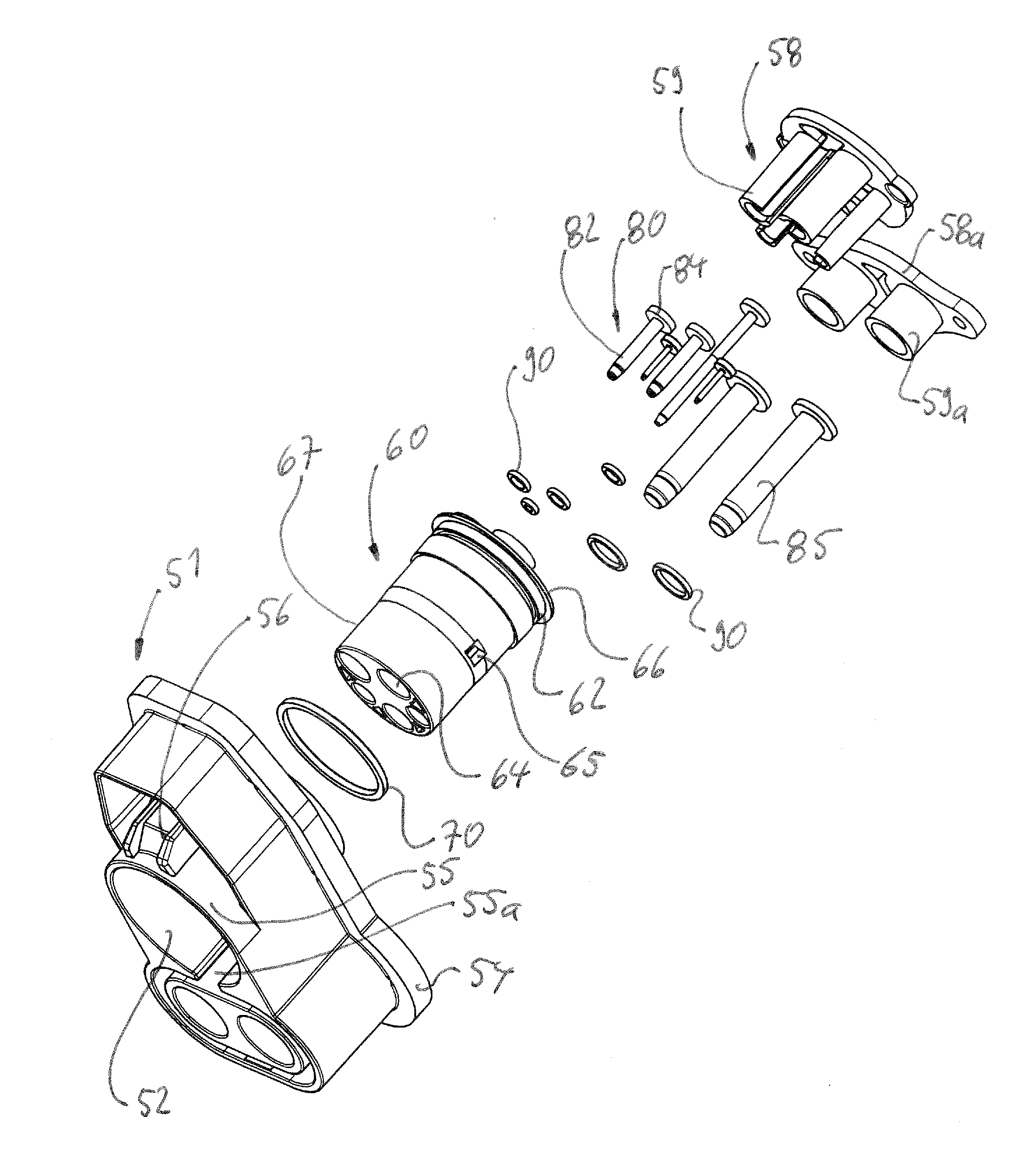
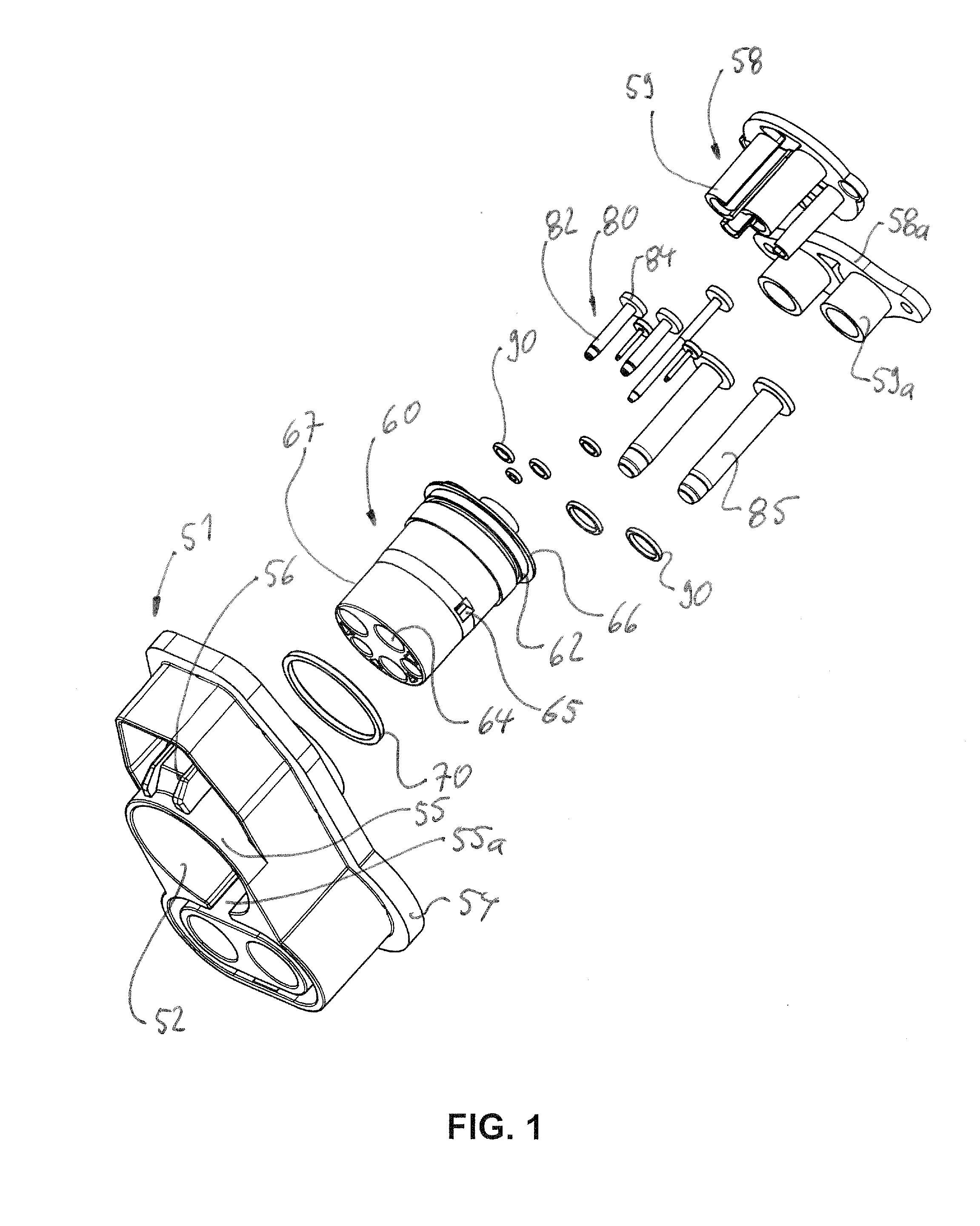
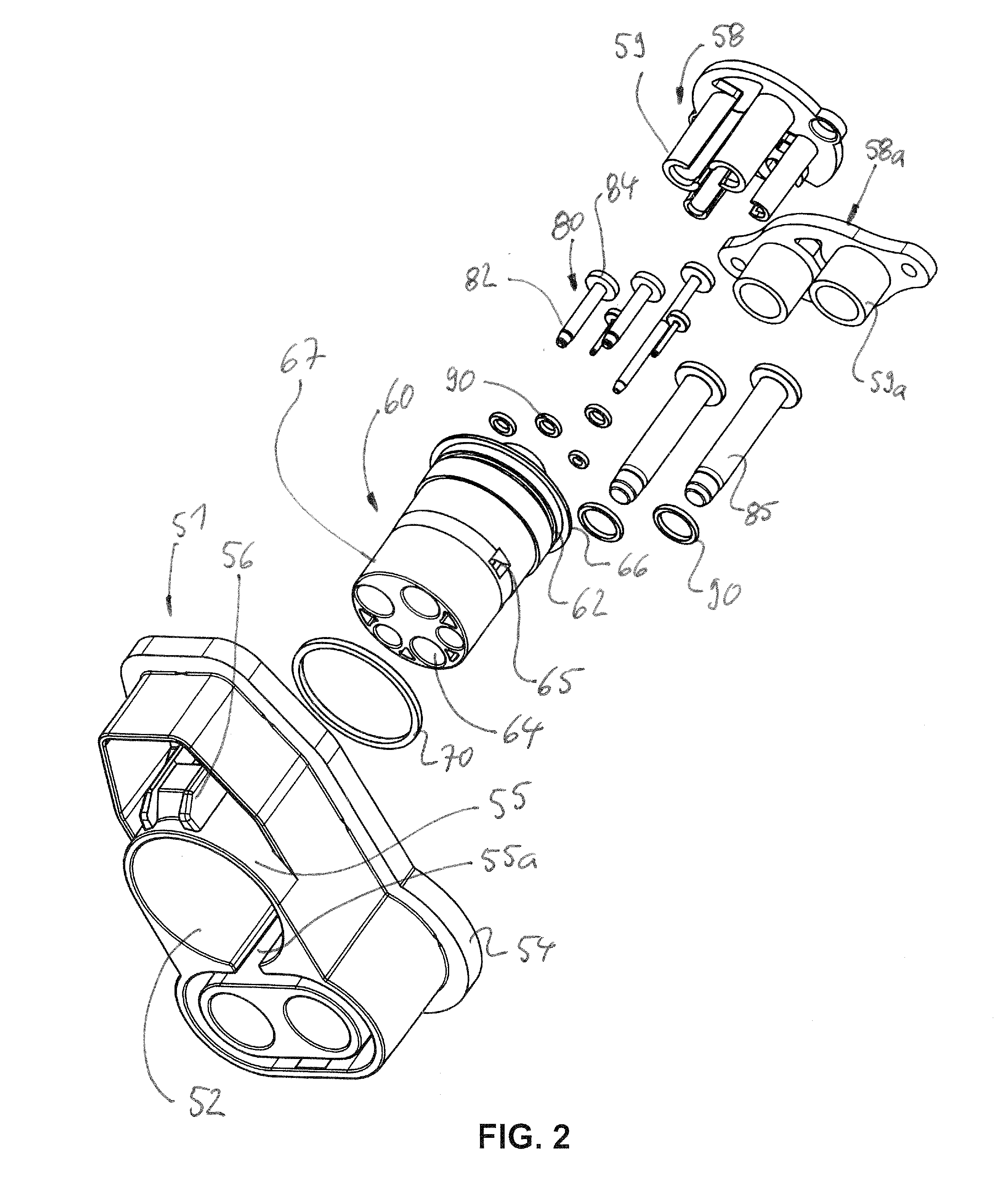
[0032]FIGS. 1 to 3 show a vehicle-side charging connector for an Electric Vehicle (EV) Conductive Charge Coupler according to one particular embodiment.
[0033]As shown in FIG. 1, the vehicle-side charging connector comprises a vehicle-side housing 51 being made e.g. of synthetic resin and / or having a mounting plate 54 to be arranged at an opening edge of a vehicle panel so as to mount the housing 51 of the connector at or in a mounting opening of the vehicle. The mounting plate 54 is preferably provided with a glue or a bonding agent such as Sikaflex® so as to bond and seal the mounting plate 54 to the opening edge of the vehicle panel. Alternatively or additionally, a separate seal may be provided, such as a silicone or rubbe...
PUM
 Abstract
Description
Claims
Application Information
 - R&D
- Intellectual Property
- Life Sciences
- Materials
- Tech Scout
- Unparalleled Data Quality
- Higher Quality Content
- 60% Fewer Hallucinations
Browse by: Latest US Patents, China's latest patents, Technical Efficacy Thesaurus, Application Domain, Technology Topic, Popular Technical Reports.
© 2025 PatSnap. All rights reserved.Legal|Privacy policy|Modern Slavery Act Transparency Statement|Sitemap|About US| Contact US: help@patsnap.com


