Hybrid drive module having a rotor secured to a hub via staking

Active Publication Date: 2016-04-14
SCHAEFFLER TECH AG & CO KG
View PDF5 Cites 43 Cited by
  • Summary
  • Abstract
  • Description
  • Claims
  • Application Information

AI Technical Summary

Problems solved by technology

The threading operation and use of a nut increases the cost, complexity, and parts count of the re

Method used


Image

  • Hybrid drive module having a rotor secured to a hub via staking
  • Hybrid drive module having a rotor secured to a hub via staking
  • Hybrid drive module having a rotor secured to a hub via staking

Examples


Embodiment Construction

[0014]At the outset, it should be appreciated that like drawing numbers on different drawing views identify identical, or functionally similar, structural elements of the disclosure. It is to be understood that the disclosure as claimed is not limited to the disclosed aspects.

[0015]Furthermore, it is understood that this disclosure is not limited to the particular methodology, materials and modifications described and as such may, of course, vary. It is also understood that the terminology used herein is for the purpose of describing particular aspects only, and is not intended to limit the scope of the present disclosure.

[0016]Unless defined otherwise, all technical and scientific terms used herein have the same meaning as commonly understood to one of ordinary skill in the art to which this disclosure belongs. It should be understood that any methods, devices or materials similar or equivalent to those described herein can be used in the practice or testing of the disclosure.

[0017...


PUM


Abstract

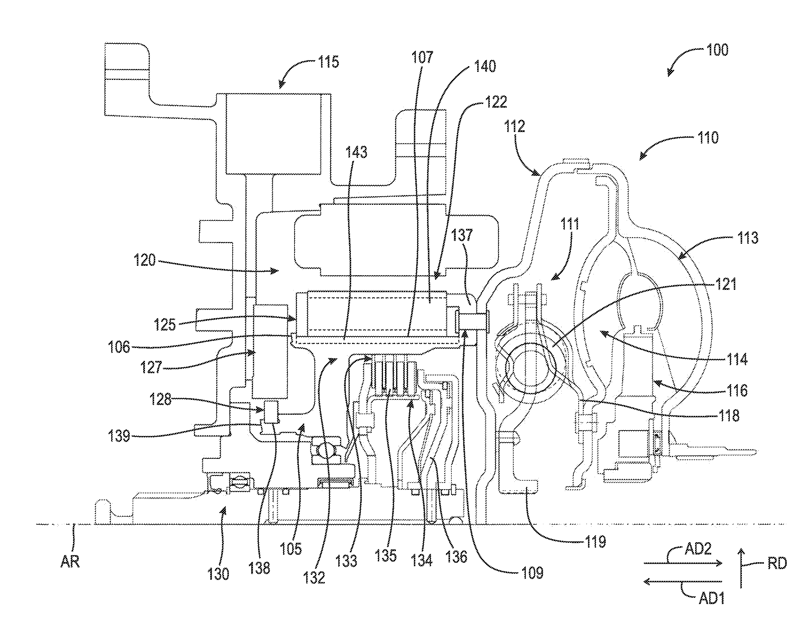
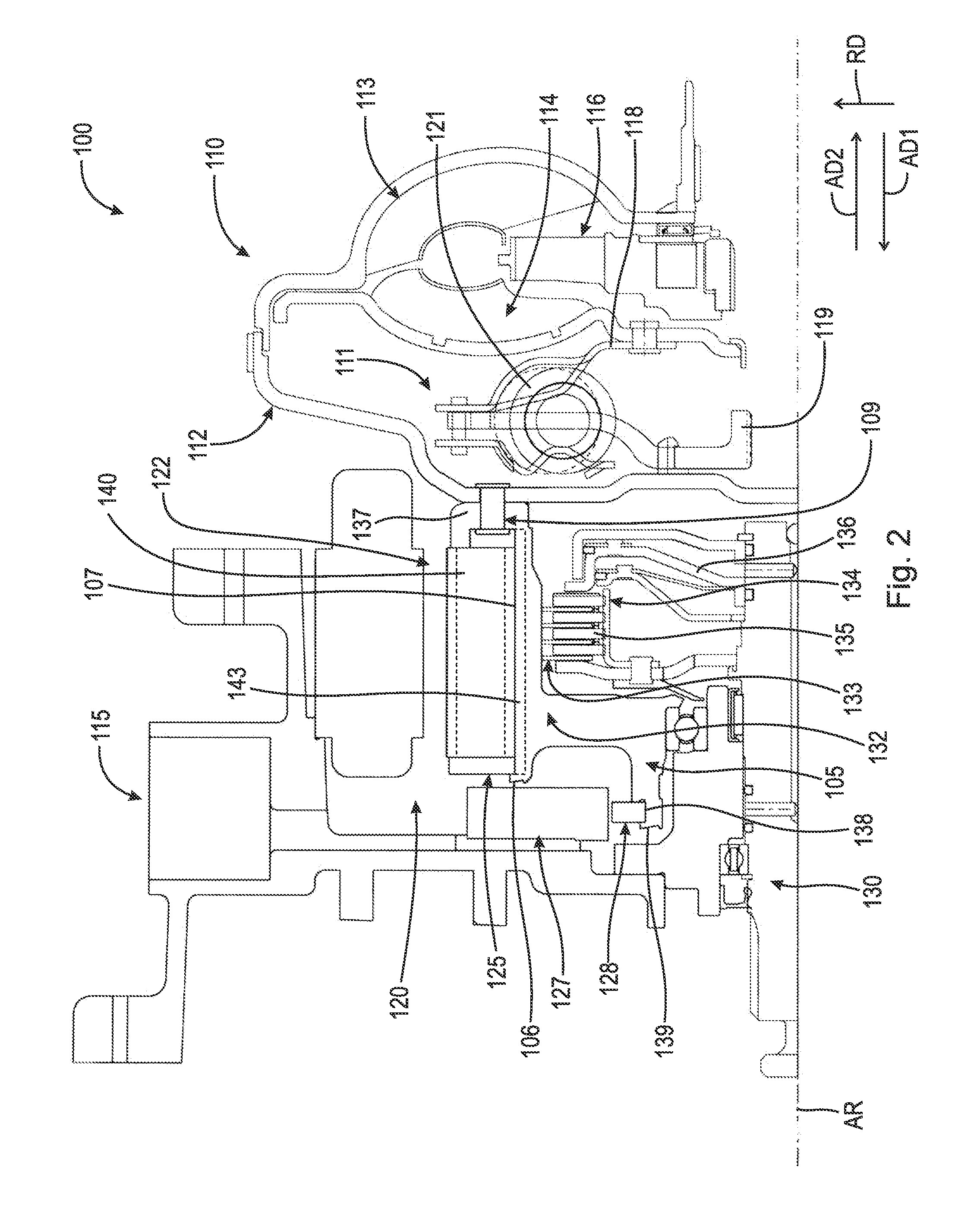
A hybrid drive module including: a torque converter with a cover, an impeller and a turbine; a rotor for an electric motor; a hub non-rotatably connected to the rotor and the cover and including a circumferential surface and a plurality of protrusions extending radially outward from the circumferential surface; and an end plate disposed between the plurality of protrusions and the rotor and engaged with the end plate and the rotor. The plurality of protrusions is formed of a material forming the hub and restrains the end plate and the rotor, with respect to the hub, in an axial direction.

Description

CROSS-REFERENCE TO RELATED APPLICATIONS[0001]This application claims the benefit under 35 U.S.C. §119(e) of U.S. Provisional Patent Application No. 62 / 061,798, filed Oct. 9, 2014, which application is incorporated herein by reference in its entirety.TECHNICAL FIELD[0002]The present disclosure relates generally to a hybrid drive module including a rotor, for an electric motor, secured to a cast aluminum hub via staking of the hub.BACKGROUND[0003]It is known to use a hybrid combination of an internal combustion engine and an electric motor to power a vehicle. For electric motor rotors designed such that an inner diameter of the rotor is a “clearance fit” (also known as a “sliding fit” or “slip fit”) about an outer diameter of a hub, a means of axially retaining the rotor on the hub is required. Typically, one side of the hub will have a formed-in flange providing axial retention for that side of the hub. However, the other side of the hub needs a means, which does not interfere with a...

Claims


Application Information

Patent Timeline
IPC IPC(8): H02K1/28H02K1/02H02K11/225H02K7/108F16D48/00H02K15/02H02K15/00B60K6/26B60K6/442H02K7/10H02K1/27
CPCH02K1/28H02K7/10H02K1/02H02K11/225H02K7/108Y10S903/902H02K15/02H02K15/00B60K6/26B60K6/442F16D48/00H02K1/27H02K7/006B60K6/40B60K6/48B60K2006/4825Y02T10/62
Inventor LINDEMANN, PATRICK M.STEINBERGER, MARKUSPAYNE, MATTHEW
Owner SCHAEFFLER TECH AG & CO KG
Why Eureka
Try Eureka