Rotating electric machine for vehicle
- Summary
- Abstract
- Description
- Claims
- Application Information
AI Technical Summary
Benefits of technology
Problems solved by technology
Method used
Image

Examples
first embodiment
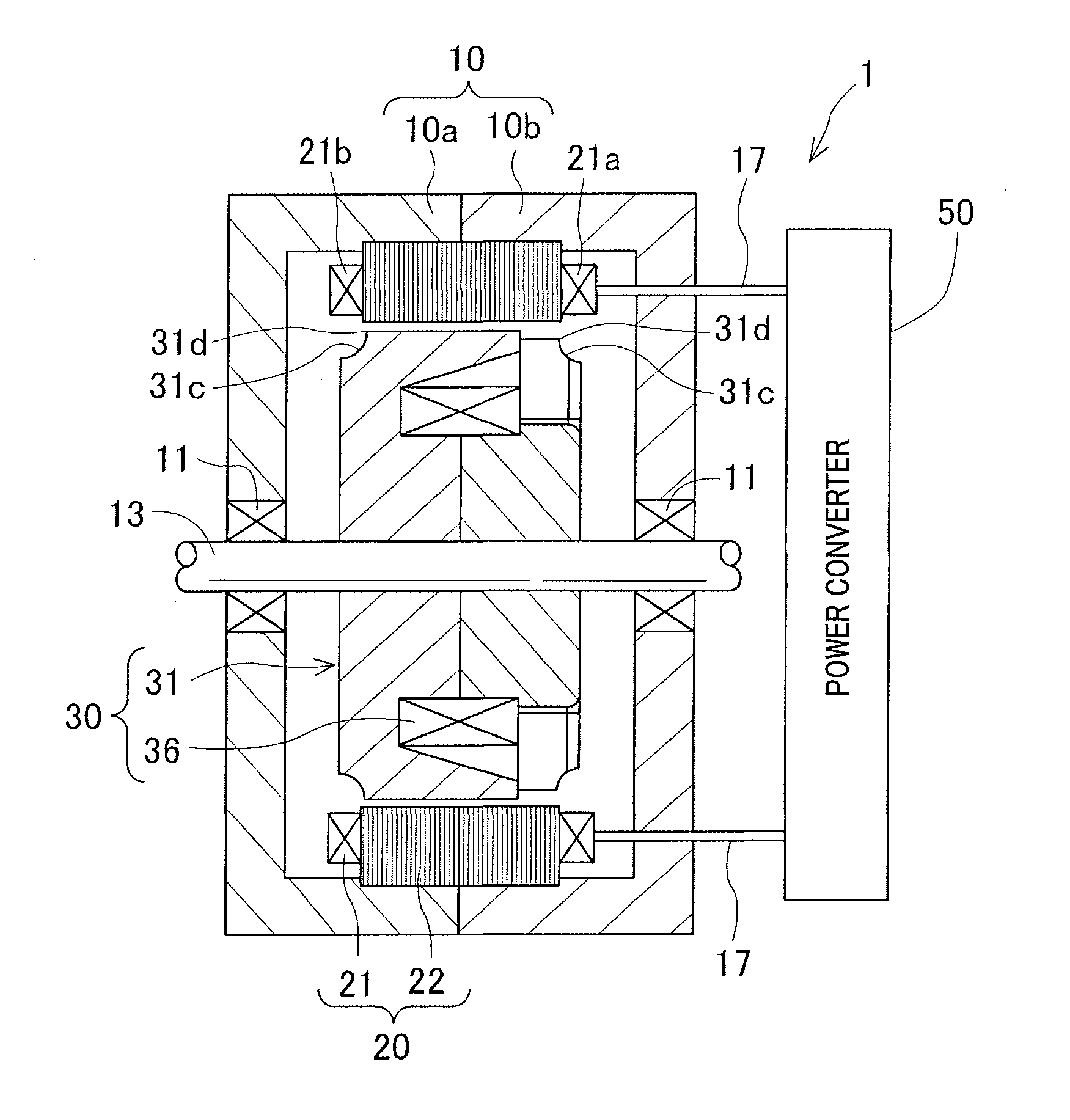
[0027]A rotating electric machine 1 in accordance with a first embodiment of the present invention is a vehicle electric motor-generator. As shown in FIG. 1, the rotating electric machine 1 includes a housing 10, a stator 20 including a stator core 22 and a stator coil 21 and operable as an armature, a rotor 30 including a Lundell rotor core 31 and a field coil 36 and operable as a field, and a power converter 50. The power converter 50 is electrically connected to the stator coil 21 and input-output lines 17 and others. The housing 10 is formed into a substantially cylindrical shape by joining openings of a pair of housing members 10a and 10b both shaped like a closed-end cylinder, opening to opening.
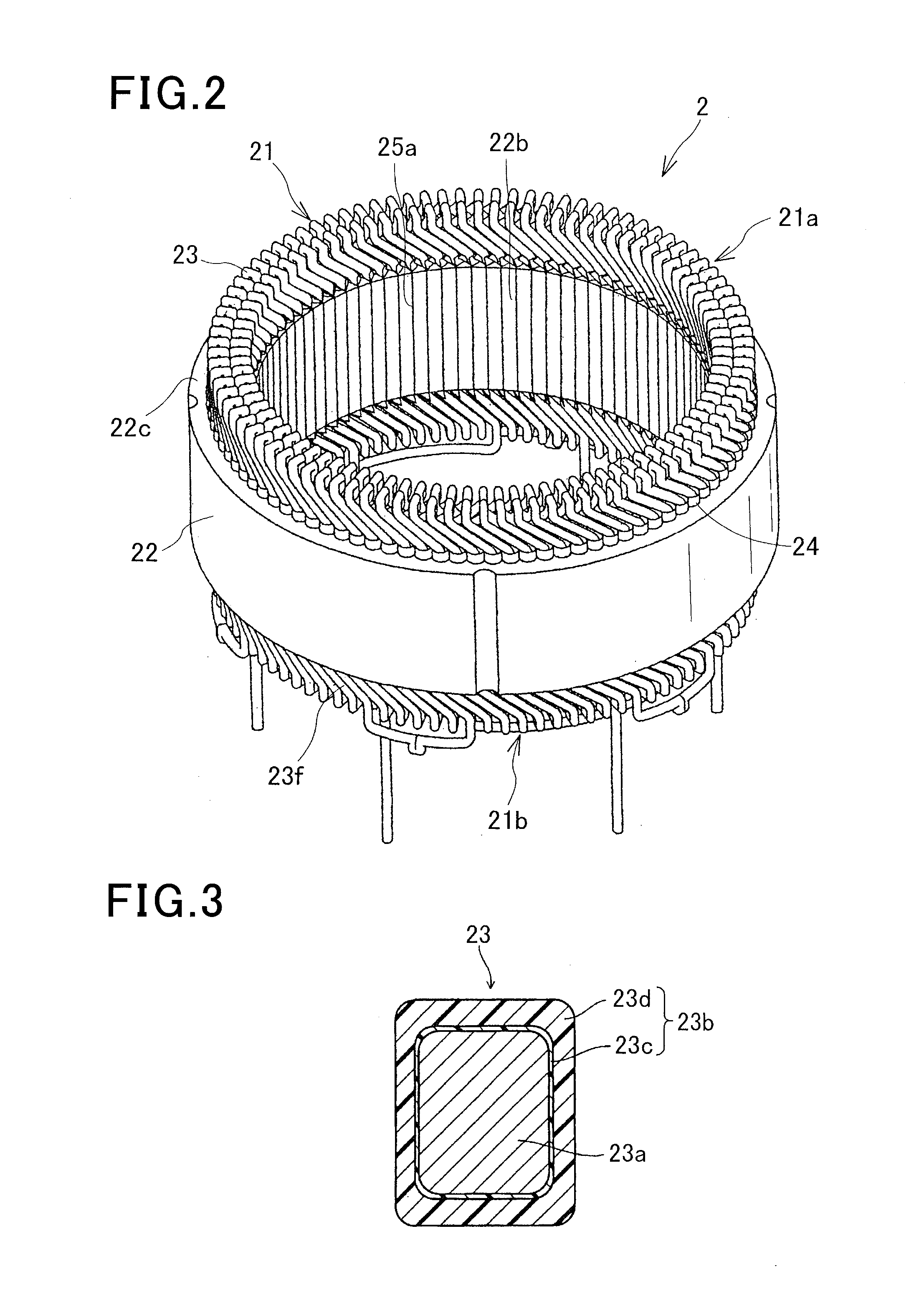
[0028]The stator 20, as shown in FIG. 2, includes an annular stator core 22 having a plurality of slots 25 circumferentially arranged in the stator core, a segmented stator coil 21 formed of a plurality of conductor segments 23, and an insulating sheet member 24 for electrically isolat...
second embodiment
[0049]A rotating electric machine in accordance with a second embodiment of the present invention will now be explained. The rotating electric machine of the second embodiment is similar in configuration to the rotating electric machine 1 of the first embodiment except in that cutout surfaces 31c of the second embodiment are different in shape from the cutout surfaces 31c of first embodiment. Only differences of the second embodiment from the first embodiment will be explained. Elements having the same functions or made of the same material as in the first embodiment are assigned the same numbers and will not be described again for brevity.
[0050]The rotor core 31 of the second embodiment is the Lundell rotor core 31 that is similar to that of the first embodiment. As shown in FIG. 11, the Lundell rotor core 31 of the second embodiment is a pairwise combination of front and rear pole cores 32. Each pole core 32, as in the first embodiment, includes a boss portion 33, a disc portion 3...
third embodiment
[0054]A rotating electric machine 2 in accordance with a third embodiment of the present invention will now be explained. The rotating electric machine 2 of the second embodiment is similar in configuration to the rotating electric machine 1 of the first embodiment except in that the rotor core 31 is not of Lundell type but includes imbedded permanent magnets 39. Only differences of the third embodiment from the first embodiment will be explained. Elements having the same functions or made of the same material as in the first embodiment are assigned the same numbers and will not be described again for brevity.
[0055]The rotor 30 of the third embodiment, as shown in FIG. 13, is rotatably supported by the housing 10 via the bearings 11 at both axial ends of the rotor 30 to rotate in unison with the shaft 13. In the housing 10, the rotor 30 and the stator core 22 are coaxially arranged and radially in a face-to-face relationship with a predetermined gap between them. The rotor 30 has an...
PUM
 Abstract
Description
Claims
Application Information
 - R&D
- Intellectual Property
- Life Sciences
- Materials
- Tech Scout
- Unparalleled Data Quality
- Higher Quality Content
- 60% Fewer Hallucinations
Browse by: Latest US Patents, China's latest patents, Technical Efficacy Thesaurus, Application Domain, Technology Topic, Popular Technical Reports.
© 2025 PatSnap. All rights reserved.Legal|Privacy policy|Modern Slavery Act Transparency Statement|Sitemap|About US| Contact US: help@patsnap.com