Suspension board with circuit

Active Publication Date: 2016-04-14
NITTO DENKO CORP
View PDF6 Cites 3 Cited by
  • Summary
  • Abstract
  • Description
  • Claims
  • Application Information

AI Technical Summary

Benefits of technology

The present invention provides a suspension board with circuit that can relax stress applied to a connecting portion between a connecting terminal of an electronic component and a terminal portion while reinforcing the terminal portion. This is achieved by forming an opening in the metal supporting board at the lower side of the connecting portion to relax the stress. The terminal portion can also be reinforced by the first and second terminal supporting portions. This results in reduced stress applied to the extended portion, further relaxing the stress on the connecting portion between the connecting terminal of the electronic component and the terminal portion.

Problems solved by technology

In such a case, there may be a case where distortion occurs in a connecting portion between the connecting terminal of the magnetic head and each terminal portion, thereby causing a crack.
However, the absence of the metal supporting board at the lower side of the above-described connecting portion reduces its rigidity, so that the application of stress to the terminal portion may deform the terminal portion.

Method used


Image

  • Suspension  board with circuit
  • Suspension  board with circuit
  • Suspension  board with circuit

Examples


first embodiment

1. Summary of First Embodiment of Suspension Board with Circuit

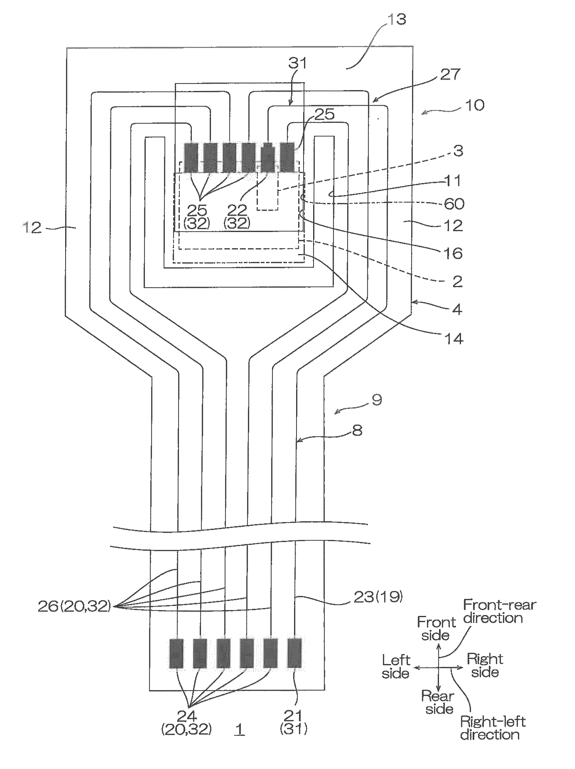
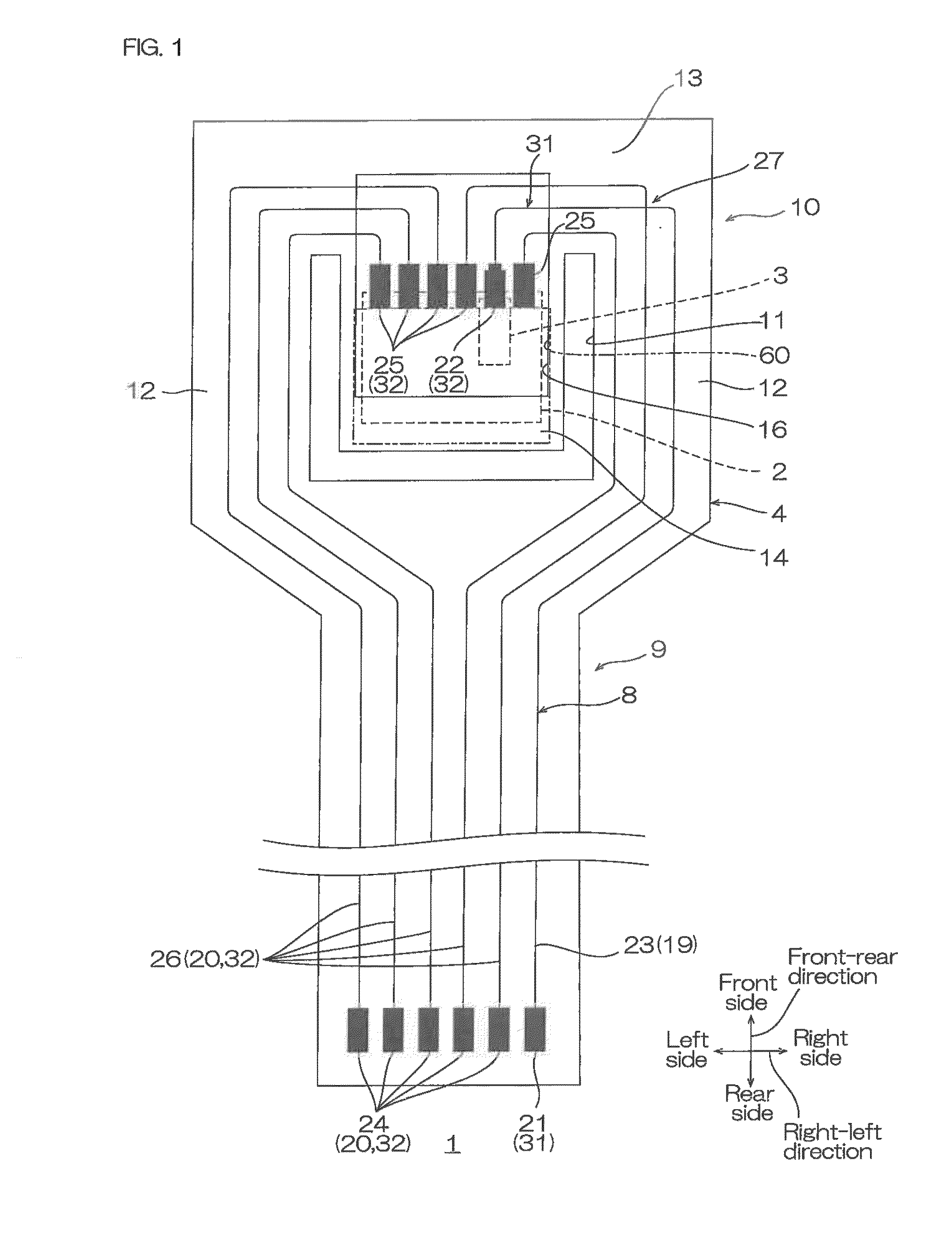
[0064]A first embodiment of a suspension board with circuit of the present invention is described with reference to FIGS. 1, 2, 3X, 3Y, and 4A to 4C.

[0065]In the following description, when referring to directions of the suspension board with circuit, the up-down direction of the paper surface in FIG. 1 is referred to as a front-rear direction (first direction); the right-left direction of the paper surface in FIG. 1 is referred to as a right-left direction (widthwise direction, second direction orthogonal to the first direction); and the direction connecting the near side of the paper surface to the far side of the paper surface in FIG. 1 is referred to as an up-down direction (thickness direction, third direction orthogonal to the first direction and the second direction). The upper side of the paper surface in FIG. 1 is referred to as a front side (one side in the first direction) and the lower side of the paper surfa...

second embodiment

(1) Second Embodiment

[0150]In the above-described first embodiment, as shown in FIG. 4C, the power source pattern 19 and the signal pattern 20 are provided in the suspension board with circuit 1.

[0151]On the contrary, in the second embodiment, the signal pattern 20 only, as a conductive pattern, is provided in the suspension board with circuit 1.

[0152]To be more specific, as shown in FIG. 9A, the signal pattern 20 in the suspension board with circuit 1 includes a first write wire 71, a second write wire 72, a first read wire 73, and a second read wire 74. The first write wire 71 and the second write wire 72 constitute a differential wire and the first read wire 73 and the second read wire 74 constitute a differential wire.

[0153]The first write wire 71 is formed of the first conductive layer 31 and is provided on the base insulating layer 5. The first write wire 71 is covered with the intermediate insulating layer 6. The second write wire 72 is provided on the intermediate insulating...

third embodiment

(2) Third Embodiment

[0161]In the above-described first embodiment, as shown in FIG. 4C, the power source pattern 19 and the signal pattern 20 are provided in the suspension board with circuit 1.

[0162]On the contrary, in the third embodiment, as a conductive pattern, the signal pattern 20 and a ground pattern 81 are provided in the suspension board with circuit 1.

[0163]To be more specific, as shown in FIG. 9B, the ground pattern 81 in the suspension board with circuit 1 is formed of the first conductive layer 31 and includes a ground wire 82 and a ground terminal 83.

[0164]The ground wire 82 is provided on the base insulating layer 5. The ground wire 82 is connected to the ground terminal 83 and a piezoelectric-side terminal that is not shown. The ground terminal 83 is connected to the metal supporting board 4. The piezoelectric-side terminal is continuous to the terminal extended portion 29 that is connected to the upper surface of the rear end portion (connecting end portion 28) of ...


PUM


Abstract

A suspension board with circuit includes a metal supporting board, a first insulating layer including a disposing portion formed at one side in a thickness direction of the metal supporting board, a first conductive layer including a first wire portion formed at the one side of the first insulating layer, a second insulating layer including a covering portion covering the first wire portion, and a second conductive layer including a second wire portion formed at the one side of the second insulating layer and a terminal portion connected to the first or second wire portion. The second insulating layer includes a second terminal supporting portion formed at the other of the terminal portion. The first insulating layer includes a first terminal supporting portion formed at the other side of the second terminal supporting portion. The metal supporting board is not formed at the other side thereof.

Description

CROSS-REFERENCE TO RELATED APPLICATION[0001]The present application claims priority from Japanese Patent Application No. 2014-209729 filed on Oct. 14, 2014, the contents of which are hereby incorporated by reference into this application.BACKGROUND OF THE INVENTION[0002]1. Field of the Invention[0003]The present invention relates to a suspension board with circuit, to be specific, to a suspension board with circuit used in a hard disk drive.[0004]2. Description of Related Art[0005]A suspension board with circuit is mounted with a slider on which a magnetic head is mounted and is used in a hard disk drive or the like. As such a suspension board with circuit, a suspension board with circuit including a metal supporting layer, a first base insulating layer formed on the metal supporting layer, a first conductive layer formed on the first base insulating layer and having a first terminal portion and a first wire, a second base insulating layer formed on the first base insulating layer s...

Claims


Application Information

Patent Timeline
IPC IPC(8): H05K1/02H05K1/11H05K1/05
CPCH05K1/0271H05K1/11H05K1/05H05K1/0298G11B5/484G11B5/4853H05K1/056H05K3/4685H05K2201/09245H05K2203/0323
Inventor SUGIMOTO, YUUTANABE, HIROYUKI
Owner NITTO DENKO CORP
Why Eureka
Try Eureka