Three-dimensional fabricating apparatus and method of fabricate three-dimensional shaped object

a three-dimensional shaped object and fabricating apparatus technology, applied in the direction of additive manufacturing processes, application, layer means, etc., can solve the problems of further increasing shaping time and time taken for movement, and achieve the effect of shortening the time required and high efficient form and stacking of powder material layers

Active Publication Date: 2016-04-21
CMET
View PDF3 Cites 26 Cited by
  • Summary
  • Abstract
  • Description
  • Claims
  • Application Information

AI Technical Summary

Benefits of technology

[0038]According to the invention, the binder liquid supply device ejecting the binder liquid is moved in the same direction as the powder material supply device so as to follow the movement of the powder material supply device supplying the powder material onto the top surface of the table, and the binder liquid is ejected onto the powder material supplied onto the top surface of the table. Thus, the ejection of the binder liquid can be performed with a slight time difference from the supply of the powder material onto the top surface of the table. For that reason, the supply of the powder material and the ejection of the binder liquid can be highly efficiently performed compared to the case where the powder material supply device or the binder liquid supply device is returned to the origin position when the operation of supplying the powder material from the powder material supply device and the operation of ejecting the binder liquid from the binder liquid supply device are switched as in the related art.
[0039]As a result, since it is possible to highly efficiently form and stack the powder material layer in a short time, it is possible to remarkably shorten a time required for making the three-dimensional shaped object.

Problems solved by technology

However, if the powder material supply device or the binder liquid supply device is returned to the origin position when the operation of supplying the powder material from the powder material supply device and the operation of ejecting the binder liquid from the binder liquid supply device are switched, a problem arises in that some time is taken for the movement.
However, the moving time of the powder material supply device or the binder liquid supply device is a factor that further increases the shaping time until the shaped object is completed.

Method used


Image

  • Three-dimensional fabricating apparatus and method of fabricate three-dimensional shaped object
  • Three-dimensional fabricating apparatus and method of fabricate three-dimensional shaped object
  • Three-dimensional fabricating apparatus and method of fabricate three-dimensional shaped object

Examples


first embodiment

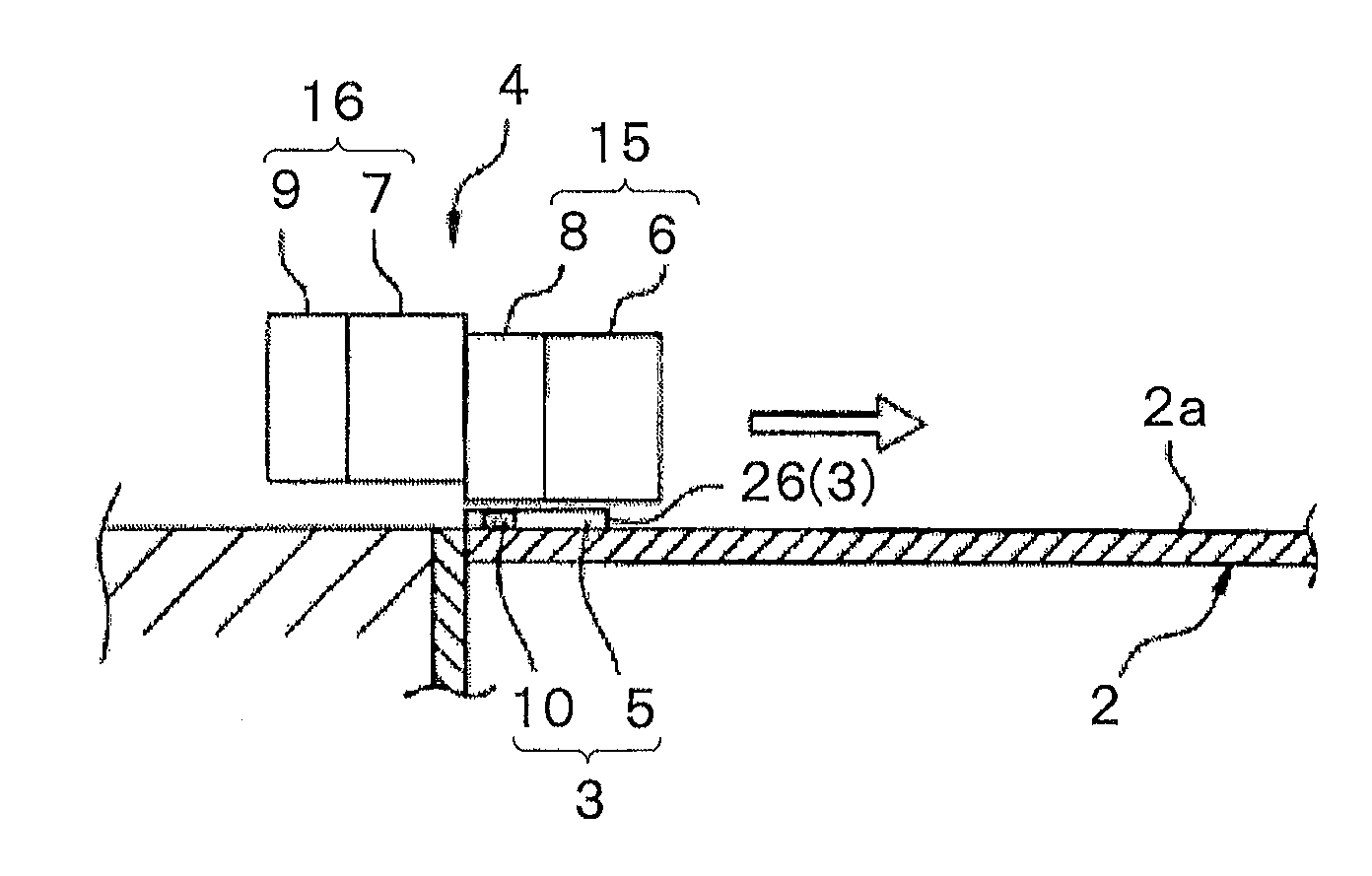
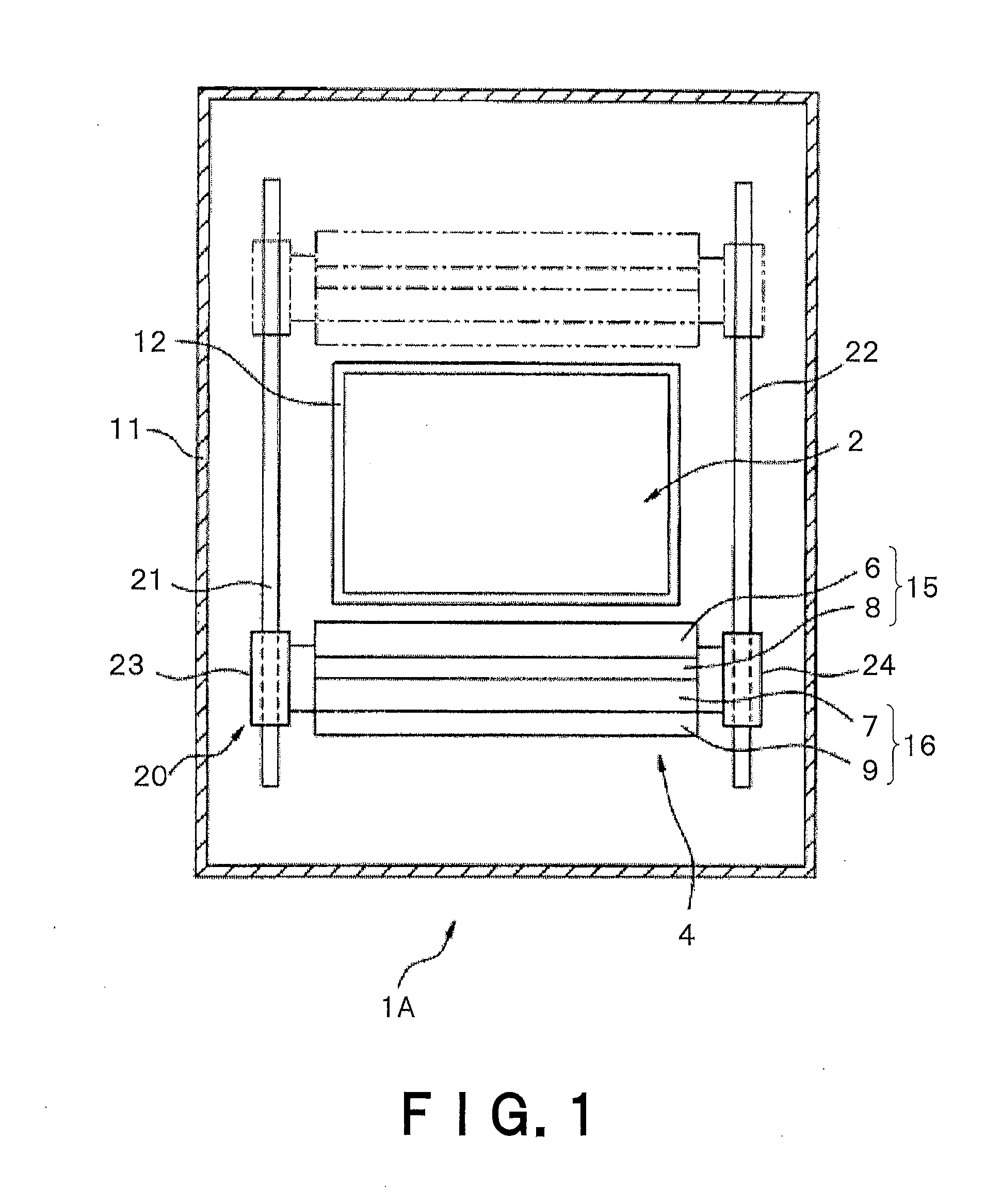
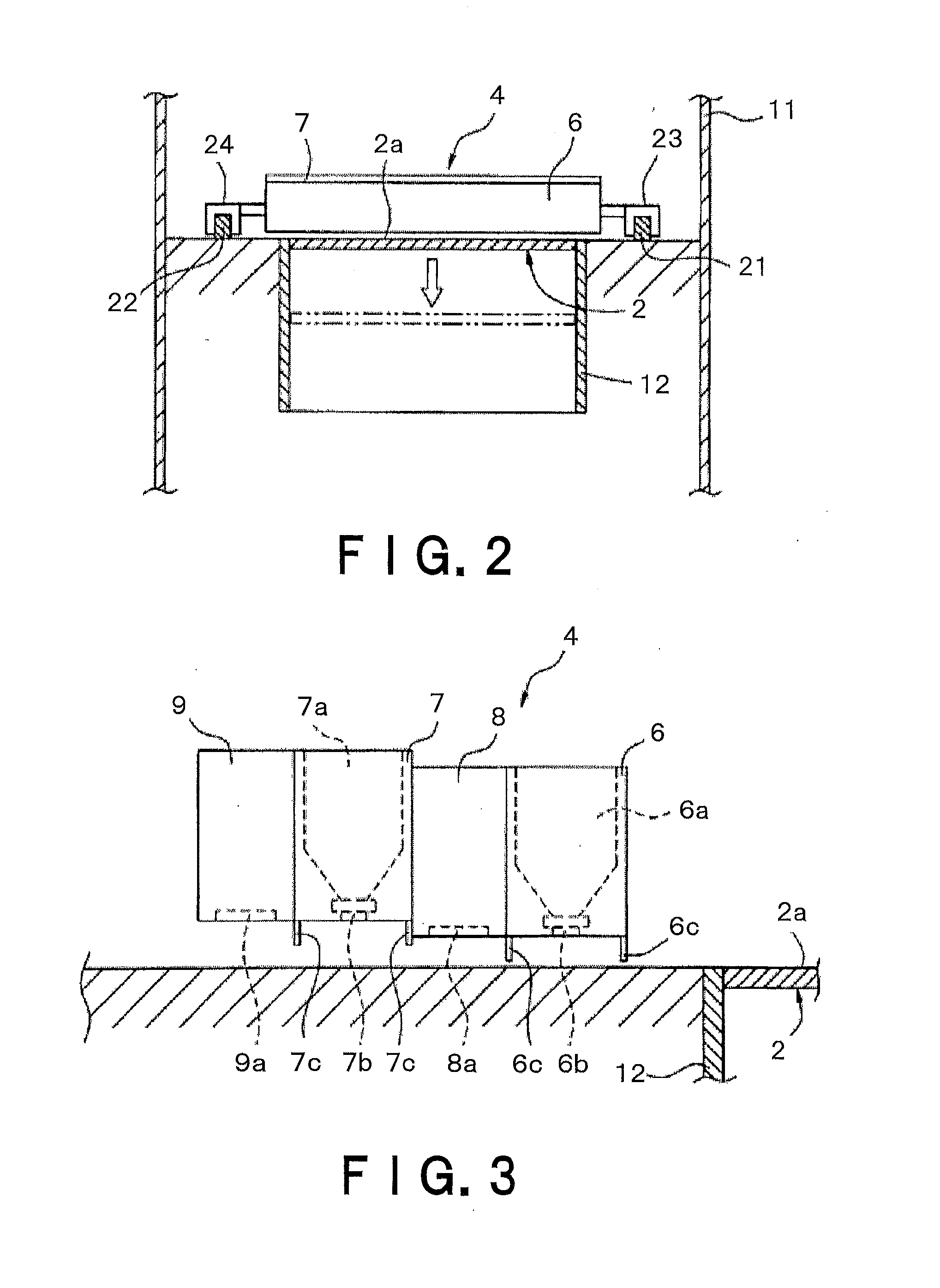
[0067]FIGS. 1, 2, 34A, 4B and 4C illustrate a three-dimensional fabricating apparatus of the invention. Here, a three-dimensional fabricating apparatus 1A of the embodiment is used to shape an object by a powder, and includes a single table 2 on which a powder material forming a three-dimensional shaped object (hereinafter, referred to as a “shaped object”) is stacked as a layer and a shaping unit 4 which forms a powder material layer 3 on a top surface 2a of the table 2.

[0068]Further, the shaping unit 4 includes a plurality of powder material supply devices 6 and 7 which supplies a powder material 5 onto the top surface 2a of the table 2 by every predetermined layer thickness and a plurality of binder liquid supply devices 8 and 9 which ejects a binder liquid to the powder material 5 supplied onto the top surface 2a of the table 2 so as to bind the powder material 5. Accordingly, when the powder material 5 is supplied from the powder material supply devices 6 and 7 onto the top sur...

third embodiment

[0326]In the third embodiment, in the shaping unit 60, the plurality of powder material supply devices 61 to 64 and the plurality of binder liquid supply devices 65 to 67 are alternately and linearly disposed in the movement direction, and the powder material supply devices 61 and 64 are located at both end sides in the movement direction. Accordingly, the powder material layer is formed during the reciprocating operation of the shaping unit, that is, both forward and backward movement operations of the shaping unit.

[0327]However, in the configuration of forming the powder material layer during both forward and backward movement operations of the shaping unit, the powder material supply devices and the binder liquid supply devices do not need to be disposed in this order, and the powder material supply devices and the binder liquid supply devices may be alternately and linearly disposed.

[0328]For example, as illustrated in FIGS. 26 and 27, a shaping unit 170 may have a configuration...

sixth embodiment

[0336]In the sixth embodiment, one powder material supply device and two binder liquid supply devices are substantially used. However, the number of the powder material supply devices and the binder liquid supply devices can be arbitrarily selected in accordance with the size of the entire three-dimensional fabricating apparatus or the size of the shaped object as the shaping target.

[0337]Further, in the sixth embodiment, one rotation member 153 is provided with the powder material supply device 154 and the binder liquid supply devices 155 and 156. However, when the powder material layers can be appropriately formed and stacked while the binder liquid supply device follows the movement of the powder material supply device, the powder material supply device and the binder liquid supply device may be respectively provided in different rotation members.

[0338]In addition, in the sixth embodiment, when the rotation member 153 provided with the powder material supply device 154 and the bi...


PUM

PropertyMeasurementUnit
diameteraaaaaaaaaa
diameteraaaaaaaaaa
diameteraaaaaaaaaa

Abstract

A three-dimensional fabricating apparatus has a table on which a powder material is stacked in a layered manner, and a shaping unit which includes a powder material supply device supplying the powder material onto a top surface of the table by every predetermined layer thickness and a binder liquid supply device ejecting a binder liquid to the powder material supplied onto the top surface of the table. The powder material supply device of the shaping unit is movable in one direction in a state adjacent to the top surface of the table and is capable of supplying the powder material onto the top surface of the table at a predetermined supply width while moving the powder material supply device. The binder liquid supply device is capable of moving in the same direction as the powder material supply device in a state adjacent to the top surface of the table.

Description

CROSS-REFERENCE TO RELATED APPLICATIONS[0001]This application is based upon and claims the benefit of priority from Japanese Patent Application No. 2013-137492 filed on Jun. 28, 2013 and PCT Application No. PCT / JP2014 / 067223 filed on Jun. 27, 2014, the entire contents of which are incorporated herein by reference.TECHNICAL FIELD[0002]The present invention relates to a three-dimensional fabricating apparatus and a method of fabricating a three-dimensional shaped object of fabricating the three-dimensional shaped object which shape the three-dimensional shaped object as a shaping target by stacking a plurality of powder material layers each of which is formed by ejecting a binder liquid to a layered powder material so as to bind the powder material.BACKGROUND ART[0003]Hitherto, a technique called rapid prototyping is widely known. Here, a three-dimensional shaped object as a shaping target is shaped by stacking layers each having a cross-sectional shape as a horizontal cross-section.[...

Claims


Application Information

Patent Timeline
Patent Type & Authority Applications(United States)
IPC IPC(8): B29C67/00
CPCB29C67/0081B33Y30/00B33Y10/00B29C64/165B29C64/205
Inventor OOBA, YOSHIKAZUSUZUKI, KOKICHIDAICHO, YUUYA
Owner CMET
Why Eureka
Try Eureka