Optical coherence tomography apparatus

a coherence tomography and optical coherence technology, applied in the field of optical coherence tomography apparatus, can solve the problems of difficult to obtain the tomographic image of the object at high speed, inability to optimally maintain the focus of the irradiation light directed on the object to be observed, and difficulty in spotting the object, etc., to achieve simplified scanning optical system, high resolution, and facilitate electronic control

Inactive Publication Date: 2010-06-10
KOWA CO LTD
View PDF5 Cites 25 Cited by
  • Summary
  • Abstract
  • Description
  • Claims
  • Application Information

AI Technical Summary

Benefits of technology

[0029]According to the present invention, two-dimensional image-capturing means is employed as a detector for detecting interference light, while means for sweeping and re-sweeping light beams are at low-speed corresponding to the frame rate of the image-capturing means. Accordingly, the scanning optical system can be simplified, and electronic control is facilitated.
[0030]Moreover, the present invention provides the effects of a confocal optical system and a low-coherence interferometer, making it possible that a tomographic image (cross-sectional image in the direction vertical to the optical axis) having a high resolution, low background noise, and high levels of contrast and gradation can be obtained at high speed in accordance with the frame rate of an image-capturing device. In particular, a calculation process for removing background light is readily performed because basically subtraction between adjacent pixels in the horizontal direction of the two-dimensional image-capturing device is used and the time difference of exposure between pixels is small. This reduces blurring of fast-moving objects, and makes it possible to observe highly accurate tomographic images on a consistent basis.
[0031]The depth scanning means can be used in combination with the above-mentioned features to enable sectional images in the direction vertical to the optical axis to be continuously acquired to form three-dimensional image information (3D images) of the interior of an object. Furthermore, the optical coherence tomography apparatus can be readily upgraded if the two-dimensional image-capturing device is changed to a high-accuracy, high-sensitivity, and high-speed device, making it possible to obtain a highly practical and economical apparatus.

Problems solved by technology

Therefore, the focus of the irradiation light (probe light) directed on the object to be observed cannot be optimally maintained for the entire region of the tomographic image, and complications are encountered in achieving higher levels of resolution in the in-plane direction orthogonal to the optical axis (depth direction).
Additionally, in the configurations shown in the above Documents, the movement of the reflective mirror in the optical path of the reference light limits the rate at which the detection signal is processed, making it difficult to obtain the tomographic image of the object at high speed.
Problems are presented with this system in that a specialized type of laser light source that can stably control the frequency of the light over a desired range is required; a light source of this type is limited in terms of variety, wavelength range, and other aspects; and the light source itself is expensive.
Advantages of this system are that the tomographic information is extracted based on numeric calculations, making mechanical scanning in the depth direction unnecessary; however, problems are presented in that the characteristics of the spectrograph limit the measurement range in the depth direction, and resolution is not readily improved in the direction orthogonal to the depth direction.
However, problems are presented in that the rate at which images are captured depends on light beam sweeping being performed over two optical axes, and the rate at which images are captured cannot readily be increased without the use of expensive modulating means or a specialized scanning system.
However, problems are presented with this system in that accurate positioning of the two CCD devices is difficult, and when a living organism or other object having a strong scatter factor is observed, the presence of strong background light superimposed as a direct-current component in the detector makes it difficult to improve the gradation of a signal component that contains tomographic information.
However, drawbacks are presented in that the light source is not used efficiently, and a high-cost, specialized switching light source or other such configuration is necessary when the system is implemented in practice.
Additionally, the system in Document D9 has the same problems as in Document D8; i.e., when a living organism or other object having a strong scatter factor is observed, the presence of strong background light superimposed as a direct-current component in the detector makes it difficult to improve the gradation of a signal component that contains tomographic information.
However, the same problems as in Document D6 are also presented in this system, insofar as the measurement range in the depth direction is limited by the characteristics of the spectrograph, and the resolution is not readily increased in the direction orthogonal to the depth direction.
However, in this system, increasing the speed of the modulating means is particularly difficult, and the time necessary to obtain one plane of a tomographic image cannot readily exceed, for example, two to three frames per second.
Therefore, a problem is presented in applications involving fast-moving living organisms.

Method used


Image

  • Optical coherence tomography apparatus
  • Optical coherence tomography apparatus
  • Optical coherence tomography apparatus

Examples


Embodiment Construction

[0042]The present invention will now be described in detail with reference to the embodiments shown in the attached drawings.

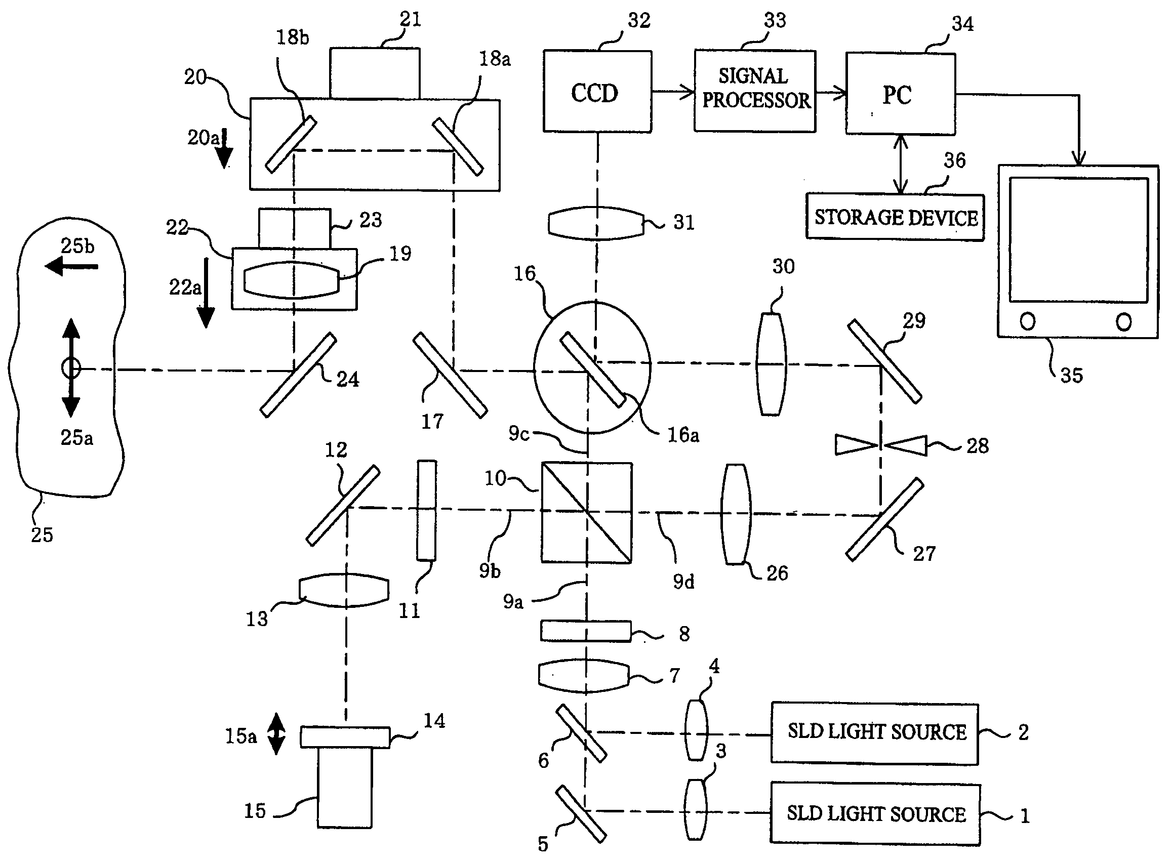
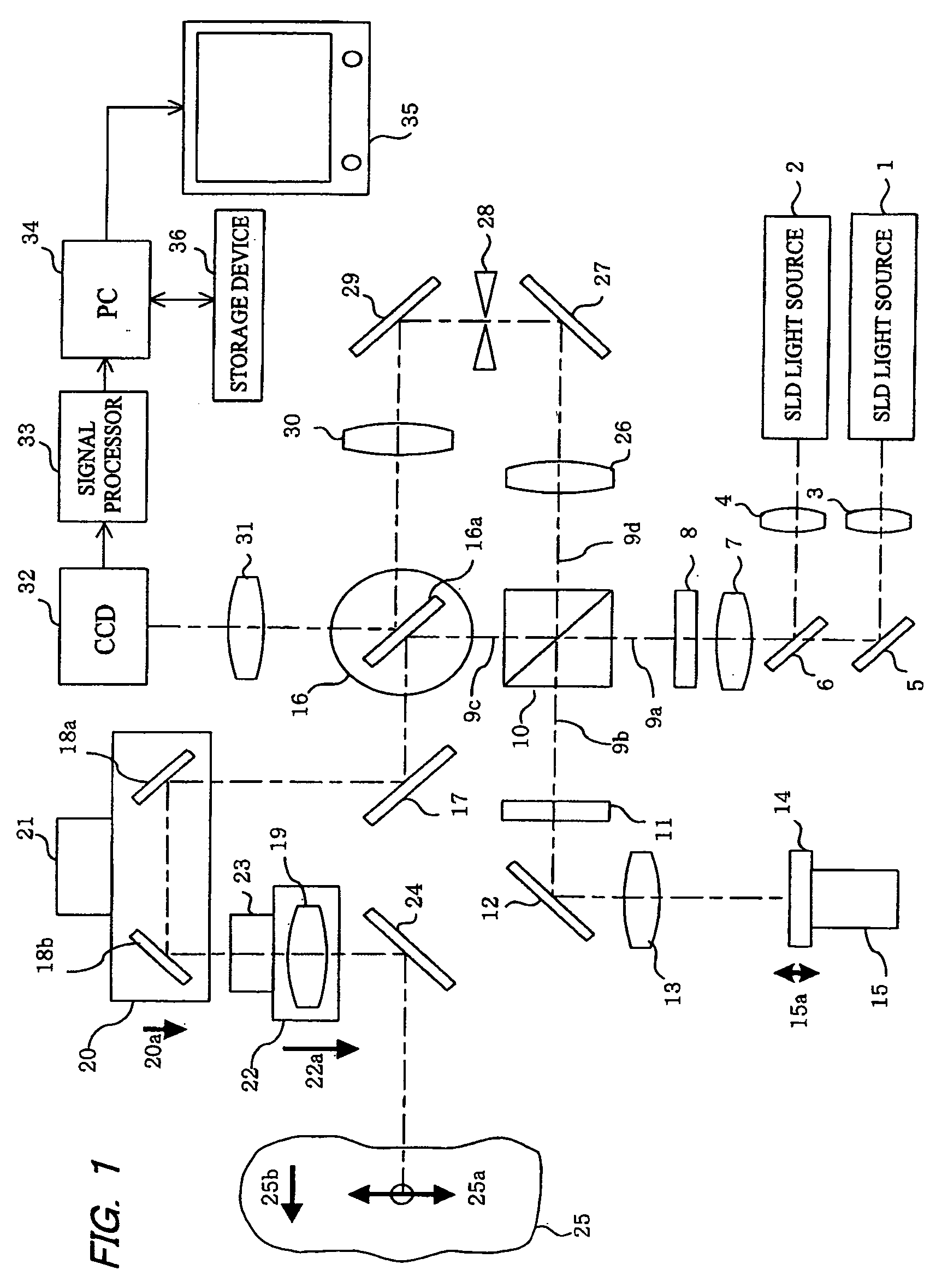
[0043]FIG. 1 shows an embodiment of an optical coherence tomography apparatus according to the invention that includes light sources 1, 2 respectively comprised of a super luminescent diode (SLD) for emitting partially coherent light having a low-coherence property (little coherence) needed for viewing tomographic images. The light sources 1, 2 generate infrared (invisible) light in different bands having central wavelengths of, for example, 830 nm and 950 nm, respectively. Light beams from the light sources 1, 2 are collimated via lenses 3, 4, and brought onto the same optical axis via a mirror 5 and a dichroic mirror 6.

[0044]It is possible for the light sources 1 and 2 to be combined as a single wide-band light source that generate two wavelength bands. Alternatively, the wavelength bands of the light sources 1, 2 may be used separately as necessary. A singl...


PUM


Abstract

An optical coherence tomography apparatus includes a light source for generating a low-coherent light beam, which is split into a probe light beam toward the object and a reference light beam toward a reference optical path. The probe light beam is swept one-dimensionally at a predetermined frequency. An interference light beam is produced by interference between the probe light beam from the object and the reference light beam that has traveled along the reference optical path. The interference light beam is re-swept in the same direction and at the same frequency as the probe light beam. A two-dimensional image-capturing device detects the re-swept interference light beam at a frame rate corresponding to the light beam sweeping frequency and produces a video signal, which is processed to provide reflection intensity information of an interior of an object to be measured. Since the two-dimensional image-capturing means is employed and interference information is obtained using low-speed beam sweeping and re-sweeping means, a scanning optical system can be straightforwardly constructed.

Description

BACKGROUND OF THE INVENTION[0001]1. Field of the Invention[0002]The present invention relates to an optical coherence tomography apparatus, and in particular relates to an optical coherence tomography apparatus wherein a light beam from a light source is swept to irradiate a predetermined area of an object to be observed, and optical interference is used to detect light reflected from the object in order to obtain tomographic information of the object.[0003]2. Description of the Prior Art[0004]Apparatuses in which interference from a low-coherent light (partially coherent light) is used to create an image from tomographic information of an object to be observed (optical coherence tomography (OCT)) have conventionally made it possible to form and observe a desired tomographic image of the object in a contactless and noninvasive manner. Accordingly, such apparatuses are particularly useful when observing living organisms, and have started to be used in routine clinical opthalmological...

Claims


Application Information

Patent Timeline
Patent Type & Authority Applications(United States)
IPC IPC(8): G01B9/02
CPCG01B9/02007G01B9/02091G01B9/02063G01B2290/65G01B9/02069G01B9/02087G01B9/02042
Inventor KOBAYASHI, KOJI
Owner KOWA CO LTD
Why Eureka
Try Eureka