Art Medium Surface Treatment Tool

a technology of surface treatment and art medium, which is applied in the direction of packaging foodstuffs, packaging goods, and chalks, can solve the problems of prolonging art projects and affecting the artist's hand and body, and achieve the effect of reducing hand and body strain

Inactive Publication Date: 2016-04-21
BUSSIE JACOB G
View PDF18 Cites 4 Cited by
  • Summary
  • Abstract
  • Description
  • Claims
  • Application Information

AI Technical Summary

Benefits of technology

[0002]The present invention relates to a device capable of applying an art medium onto and/or manipulating an art medium on a substrate and reduces hand and body strain associated with r

Problems solved by technology

Application of these mediums to, or modification of such medium after application to, a substrate can leave the artist with hand and body strain as the repeated twisting, oscillating, and/or re

Method used


Image

  • Art Medium Surface Treatment Tool
  • Art Medium Surface Treatment Tool
  • Art Medium Surface Treatment Tool

Examples


first embodiment

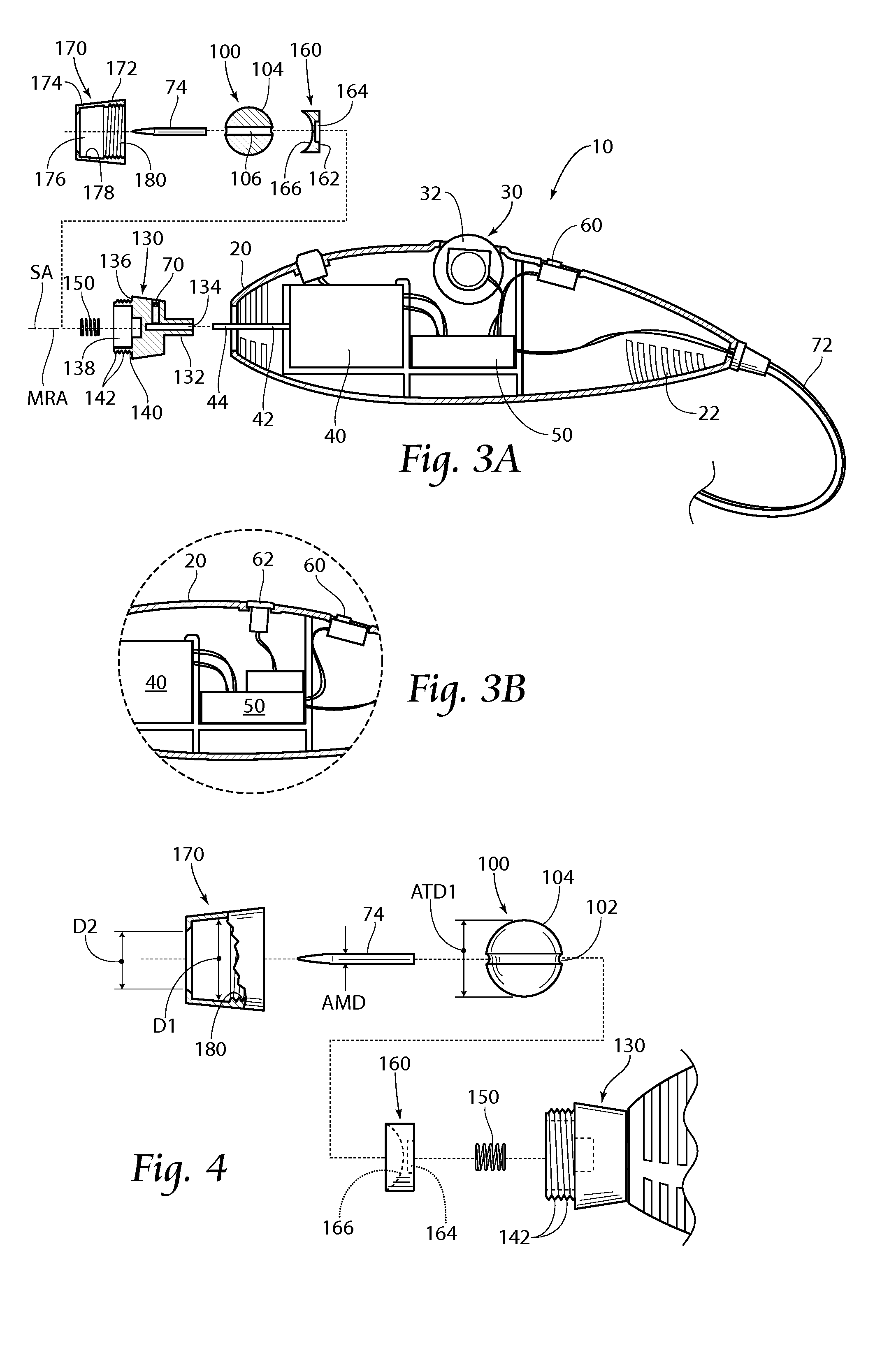
[0035]The first embodiment applicator tip 100 is shown more clearly in FIGS. 3A and 4-5B. The applicator tip 100 is preferably spherical with a diameter ATD1 and comprises a material having an elastic characteristic, as a non-limiting example, silicone. The applicator tip 100 preferably comprises a groove 102 about the periphery 104 along a circumference (e.g., the great circle) of the applicator tip 100. At least one substantially cylindrical cavity 106 having a diameter CD (see FIGS. 5A and 5B, CD′ and CD″, respectively) may be located within the groove 102 and preferably extends radially inward. The groove 102 preferably has a semi-circular profile with a diameter GD (see FIGS. 5A and 5B, GD′ and GD″, respectively). The groove diameter GD is preferably substantially the same dimension as the cavity diameter CD.

[0036]It is contemplated that various embodiments of the applicator tip 100 may be configured for various art mediums 74 based on the type of medium and / or the diameter of ...

second embodiment

[0053]A method for attaching the art medium 74 to the second embodiment applicator tip 200 and tool 10 is shown in FIGS. 15-18. The method comprises providing a plurality of art mediums 74 in a tray 76, inserting one of the art mediums 74 into the hole 206 of the applicator tip 200 (FIG. 15), receiving the shaft 42 within the coupling assembly bore 234 and securing the coupling assembly 220 to the shaft 42 with set screw 70, and inserting the applicator tip 200 within the coupling assembly pocket 238 (FIG. 16), shown fully assembled in FIG. 17.

embodiment 42

[0054]A second shaft embodiment 42′ is shown in FIG. 13B. The shaft 42′ has an attachment portion 44′ offset from the motor rotational axis MRA. Depicted here, the attachment portion 44′ may be substantially parallel with the motor rotational axis MRA, but it is contemplated that the shaft attachment portion 44′ may be disposed an angle from 0° to 90° measured from the motor rotational axis MRA.

[0055]It is contemplated that the shaft 42, 42′ may be fluted or comprise a keyway to receive splines or a key in the coupling assembly bore 134, 234.

[0056]As shown in FIG. 19, a foot pedal 64 may be incorporated in series with the cord 72 connecting the tool 10 to the power source (not shown). The foot pedal 64 may be used as an on / off switch additionally or alternatively to the other power switch 60 or optical sensor 62 and / or the foot pedal 64 may be used as a speed control in a manner similar to that of the motor speed control 30 disclosed above

[0057]FIGS. 20A-20E depict various embodimen...


PUM

PropertyMeasurementUnit
Lengthaaaaaaaaaa

Abstract

An art medium applicator includes a rotating shaft and an art medium coupled thereto for causing the medium to travel through an application path for transfer to a substrate. The applicator includes a coupling assembly, and may include an applicator tip including a cavity into which the art medium is inserted and supported. An art medium modifier includes a rotating shaft and an art medium modifier coupled thereto for causing the modifier to travel through an application path for modification of an art medium previously applied to a substrate.

Description

BACKGROUND OF THE INVENTION[0001]Application of an art medium, such as ink, paint, graphite, charcoal, crayons, chalks, pastels, gum-, resin-, or wax-based or -impregnated pigmented pencil cores, etc., both by hand and with an applicator, are well known in the world of art. Application of these mediums to, or modification of such medium after application to, a substrate can leave the artist with hand and body strain as the repeated twisting, oscillating, and / or reciprocating motion used to apply them is very taxing. Additionally, as the hand and body tire or age, extended time periods of application are difficult to achieve, thus prolonging art projects. The field of art medium application and manipulation would benefit from a device that applies and manipulates art medium on a substrate with reduced wear on the artist.SUMMARY OF THE INVENTION[0002]The present invention relates to a device capable of applying an art medium onto and / or manipulating an art medium on a substrate and re...

Claims


Application Information

Patent Timeline
IPC IPC(8): B43L13/24B43K19/02B43K23/016B43K19/00
CPCB43L13/24B43K19/003B43K23/016B43K19/006B43K19/02B43K19/00B43K23/00B43K24/14B44B11/02B44D5/10
Inventor BUSSIE, JACOB G.
Owner BUSSIE JACOB G
Why Eureka
Try Eureka