

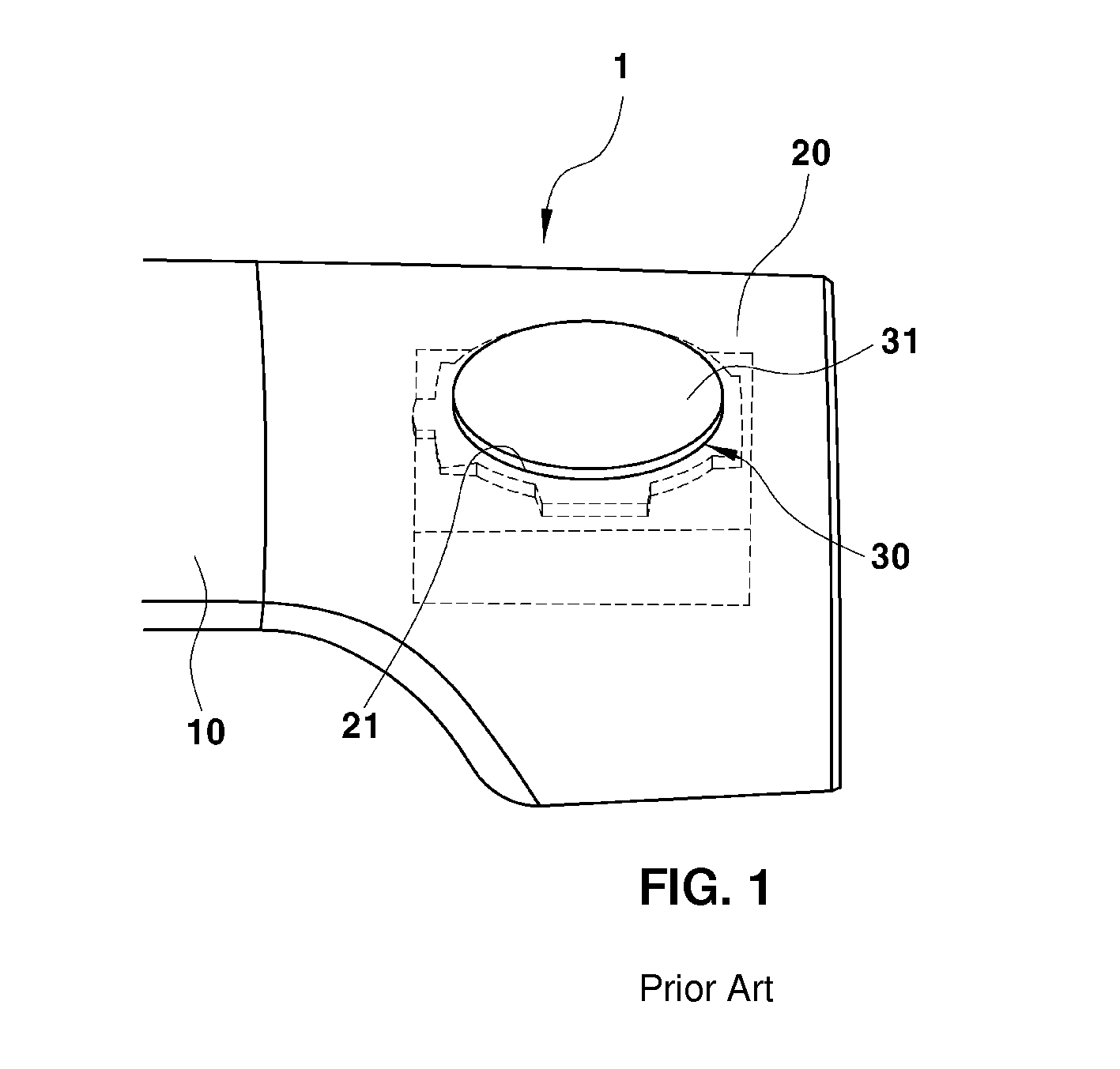
Push switch of outside handle of door
- Summary
- Abstract
- Description
- Claims
- Application Information
AI Technical Summary
Benefits of technology
Problems solved by technology
Method used
Image

Examples
Embodiment Construction
[0042]Hereinafter, the present inventive concept will be described in detail so that those skilled in the art to which the present disclosure pertains can easily carry out the present inventive concept.
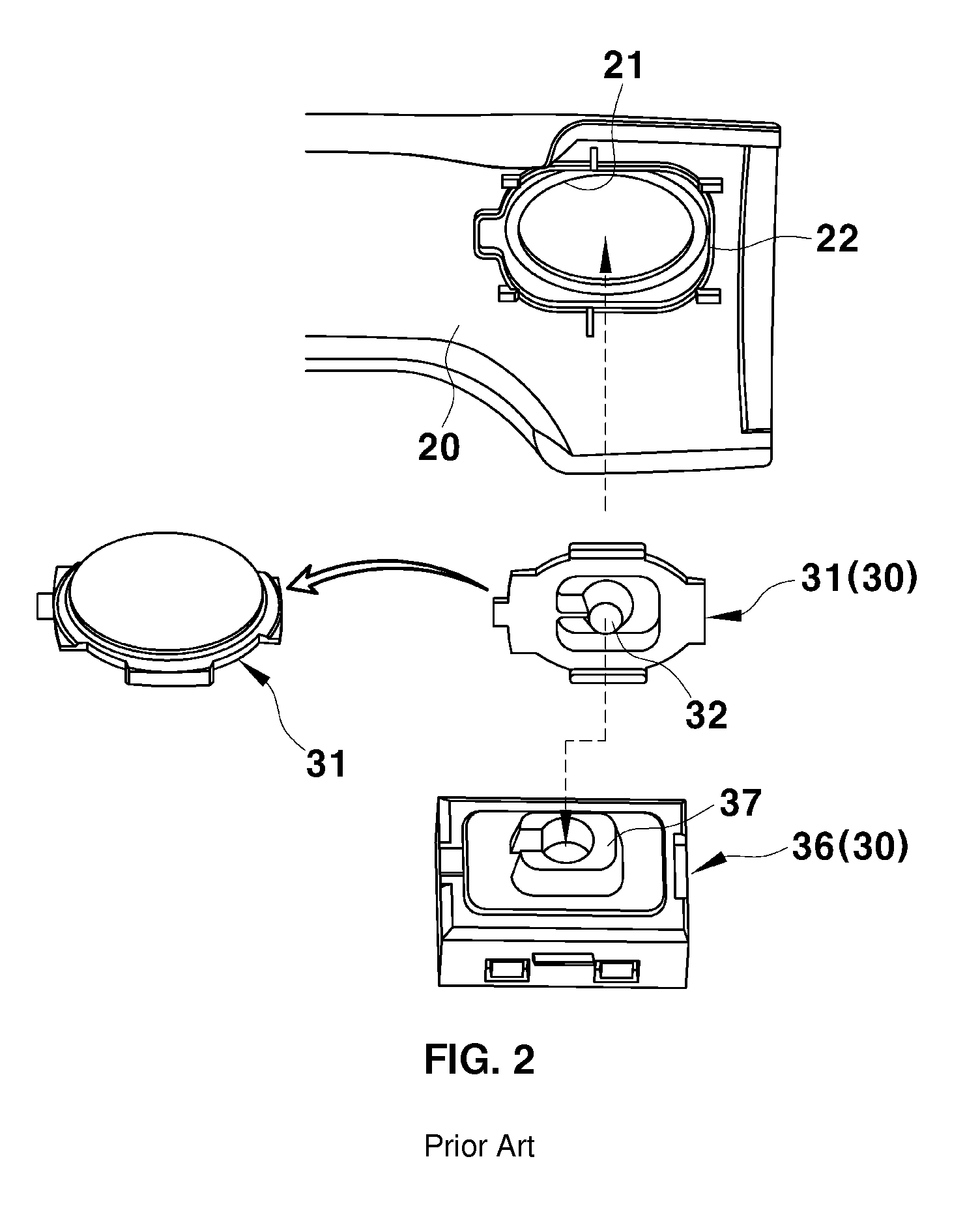
[0043]FIG. 5 is a view showing a push switch 30 according to an embodiment of the present disclosure in which a grip cover 20, a button 31, and a tact switch 36 are separated.
[0044]FIG. 6 is a perspective view showing a button 31 of the push switch 30 according to an embodiment of the present inventive concept. FIG. 7 is a cross-sectional view showing an assembly of the button 31 and the tact switch 36.
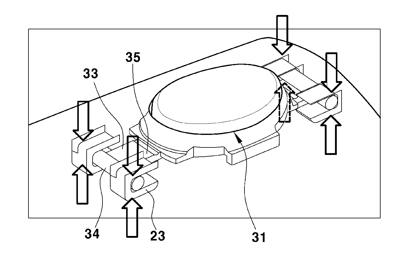
[0045]As shown in FIG. 5, the push switch 30 according to the present disclosure includes the button 31 installed inside the grip cover 20. The button 31 is exposed to the outside through a hole 21 of the grip cover 20 and the tact switch 36 is pressed and operated by a push protrusion 32 of the button 31 when the button 31 is pushed.
[0046]The push switch 30 of the present disclosure is...
PUM
 Abstract
Description
Claims
Application Information