Motor-gear unit as well as wheel-hub drive having such a motor-gear unit

a motor-gear unit and wheel-hub technology, applied in the direction of transportation and packaging, transportation, cycles, etc., can solve the problems of compact construction and relatively large size, and achieve the effects of convenient operation, simple and compact design, and favorable gear ratio rang

Inactive Publication Date: 2016-04-28
ROBERT BOSCH GMBH
View PDF10 Cites 7 Cited by
  • Summary
  • Abstract
  • Description
  • Claims
  • Application Information

AI Technical Summary

Benefits of technology

[0003]In contrast, the motor-gear unit according to the present invention has the advantage that the electric motor of the motor-gear unit is able to be operated efficiently in the largest possible rpm band. In the present invention, this is achieved in that the electric motor can be operated in two directions by reversing the direction of rotation, a first gear ratio being provided in a first direction of rotation, and a second gear ratio, which differs from the first gear ratio, being provided in a second direction of rotation. Two gear stages are therefore available, a first gear stage, which has a first freewheel, being provided in a first direction of rotation, and the second gear stage, which has a second freewheel, being provided in a second direction of rotation that runs counter to the first direction. Depending on the direction of rotation of the electric motor, only one of the two gear stages is consequently active in each case, while the other is inactive via the freewheel. By reversing the direction of rotation, the motor-gear unit according to the present invention may have two different gear stages, despite the very simple and compact design of the motor-gear unit. Because of the two freewheels, each blocking or releasing in a different direction, only one gear stage becomes active, depending on the direction of rotation, so that a favorable gear ratio range is able to be selected as a function of the rotational speed of the electric motor. No actuators or similar devices are required for changing the gear ratio; instead, the electric motor is able to be controlled simply by a modified actuation, i.e., its direction of rotation, in order to allow a change in the rotational speed. The change in the direction of rotation is easily specifiable by a controller.

Problems solved by technology

However, one problem of such wheel-hub drives in electric bicycles is their relatively large size.
This results in an especially compact construction.

Method used


Image

  • Motor-gear unit as well as wheel-hub drive having such a motor-gear unit
  • Motor-gear unit as well as wheel-hub drive having such a motor-gear unit
  • Motor-gear unit as well as wheel-hub drive having such a motor-gear unit

Examples


Embodiment Construction

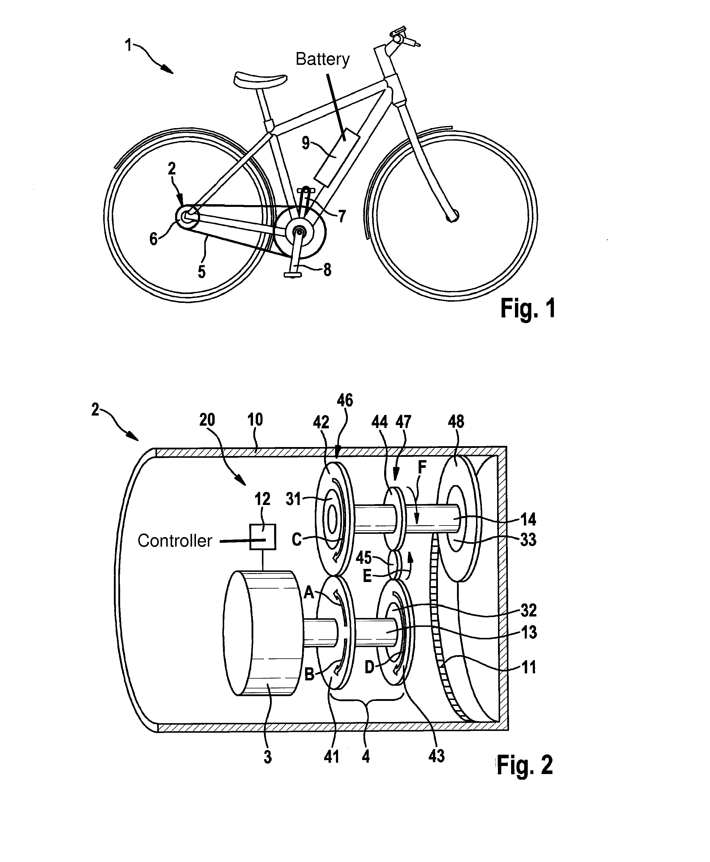
[0018]An electric bicycle 1 having a motor-gear unit 20 according to the present invention is described in detail below, with reference to FIGS. 1 to 3. As is clear from FIG. 1, electric bicycle 1 includes a wheel-hub drive 2, which is connected to a battery 9. Via cranks 7, 8, a bicycle is able to drive a chain 5, which can output a torque to the rear wheel via a pinion 6 on the rear wheel.

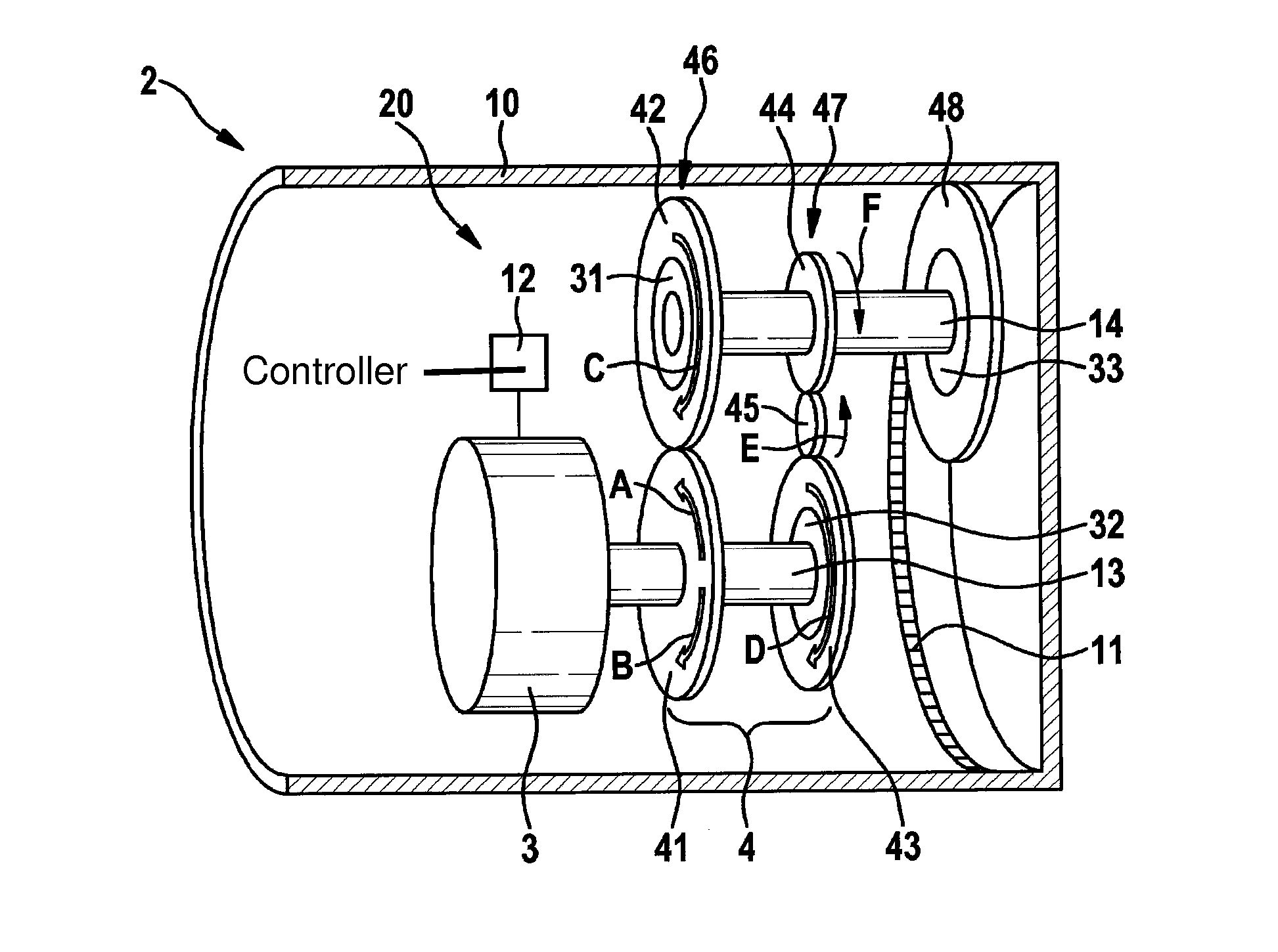
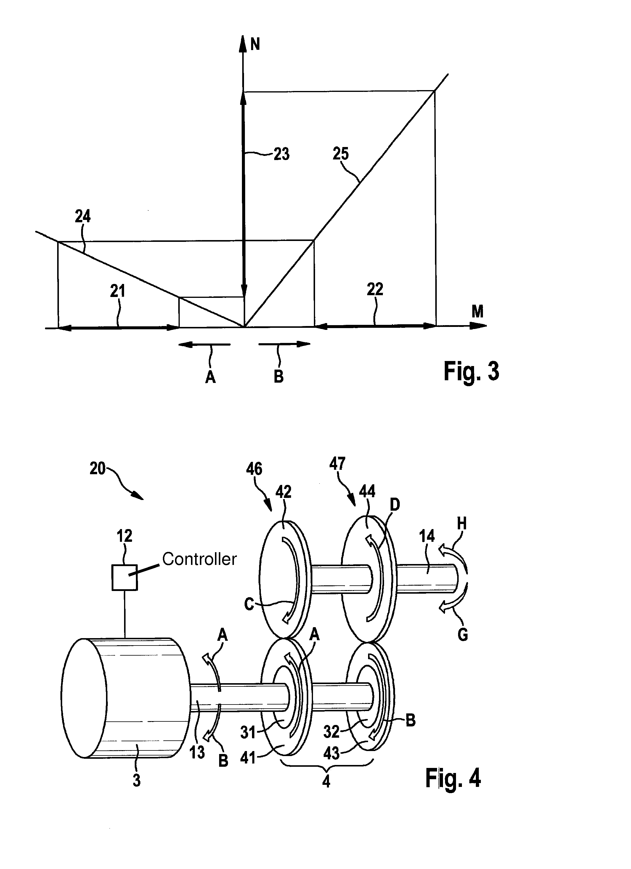
[0019]Wheel-hub drive 2 is shown in detail in FIG. 2. Wheel-hub drive 2 includes a wheel hub 10 and motor-gear unit 20. Motor-gear unit 20 encompasses an electric motor 3 and a gear unit 4. Gear unit 4 has a first gear stage 46 and a second gear stage 47.

[0020]First gear stage 46 includes a first gear wheel 41, which is disposed on an input shaft 13 of gear unit 4, and a second gear wheel 42, which is disposed on a driven shaft 14 of the gear unit. In addition, a first freewheel 31 is situated at second gear wheel 42. First freewheel 31 ensures that second gear wheel 42 is carried along in one di...


PUM


Abstract

A motor-gear unit is provided, including a motor, preferably an electric motor, having a first and second drive direction, a gear unit which is situated directly on the motor and includes an input shaft and a driven shaft as well as a controller, which is set up to drive the motor in the first and second drive direction, the gear unit having a first gear stage and a second gear stage, which feature different gear ratios, the first gear stage having a first freewheel and the second gear stage having a second freewheel, and a freewheel direction and a blocking direction of the first freewheel and the second freewheel are different.

Description

FIELD OF THE INVENTION[0001]The present invention relates to a compact motor-gear unit, in which a gear unit is situated directly on a motor, such as an electric motor. In the following text reference is always made to electric motors, although the present invention is not restricted to such motors. In addition, the present invention relates to a wheel-hub drive including a motor-gear unit of this type, and to a vehicle, in particular an electric bike having such a wheel-hub drive.BACKGROUND INFORMATION[0002]Compact motor-gear units, which are also referred to as geared motors, are known from the related art. Here, a gear unit which is situated directly on the electric motor reduces an output rotational speed in order to increase in particular an output torque of the electric motor. In addition, wheel-hub drives are known, for instance in connection with electric bicycles, which are installed in a wheel hub. However, one problem of such wheel-hub drives in electric bicycles is their...

Claims


Application Information

Patent Timeline
Patent Type & Authority Applications(United States)
IPC IPC(8): B60K17/14B60K17/04F16H3/00B60K17/26B62M6/60B62M11/04B60K7/00B60K17/06
CPCB60K17/145B60K7/0007B60K17/043F16H3/003B60K17/26B62M6/60B62M11/04B60K17/06B60K2007/0061B60Y2200/13B62M11/06
Inventor ENGELBERG, RALPH
Owner ROBERT BOSCH GMBH
Why Eureka
Try Eureka