Eureka AIR delivers breakthrough ideas for toughest innovation challenges, trusted by R&D personnel around the world.

System and method for controlling bonding material in a wind turbine blade

Active Publication Date: 2016-04-28
GENERAL ELECTRIC CO
View PDF9 Cites 4 Cited by
  • Summary
  • Abstract
  • Description
  • Claims
  • Application Information

AI Technical Summary

Benefits of technology

The present patent describes a wind turbine blade design that includes a bonding material to join two shell members together, with a constrainer to prevent the bonding material from spreading into the blade interior. This design allows for improved bonding and reduced risk of damage to the blade during assembly. The technical effect of this patent is to provide a wind turbine blade that is more durable and reliable.

Problems solved by technology

This excess bonding paste leads to a larger bond width and may incur additional material cost.

Method used


Image

  • System and method for controlling bonding material in a wind turbine blade
  • System and method for controlling bonding material in a wind turbine blade
  • System and method for controlling bonding material in a wind turbine blade

Examples


Embodiment Construction

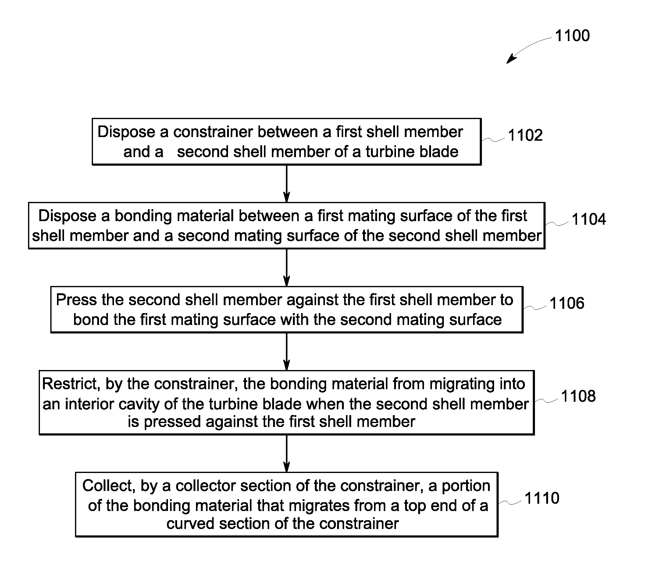
[0017]As will be described in detail hereinafter, various embodiments of exemplary systems and methods for bonding an upper shell member to a lower shell member of a wind turbine blade are presented. In particular, the systems and methods presented herein aid in restricting bonding paste from migrating into the interior cavity of turbine blades. By employing the methods and the various embodiments of the systems of the present specification, migration of the bonding paste into an interior cavity of the wind turbine blades may be minimized or ceased completely. This in turn improves the bond width control and reduces unnecessary material waste.

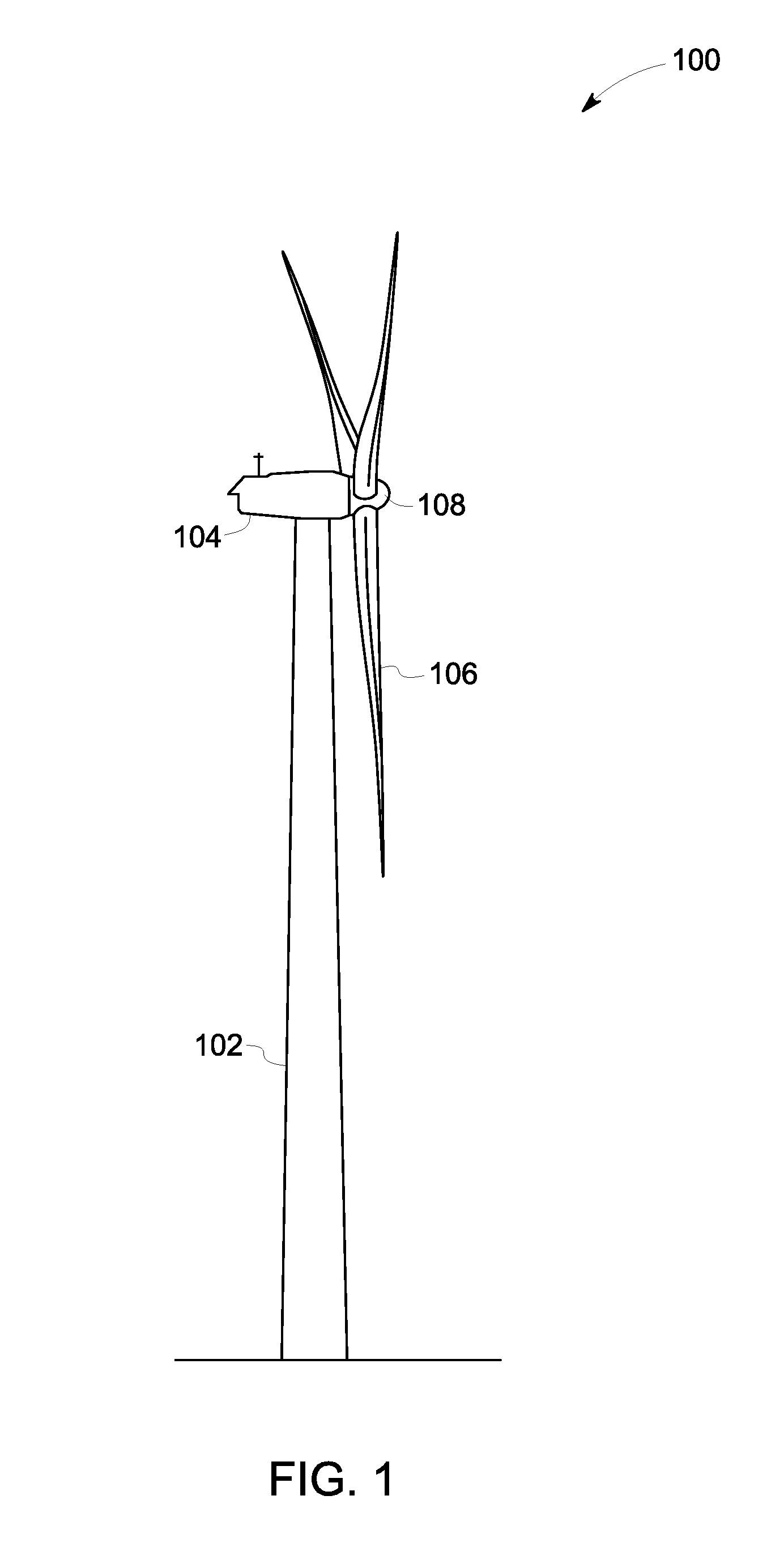
[0018]Turning now to the drawings and referring to FIG. 1, a diagrammatical representation of a wind turbine 100, in accordance with aspects of the present specification, is depicted. The wind turbine 100 is used to covert wind energy into electrical energy. As depicted in FIG. 1, the wind turbine 100 includes a tower 102 with a nacelle 104 mou...


PUM

PropertyMeasurementUnit
Forceaaaaaaaaaa
Flexibilityaaaaaaaaaa
Areaaaaaaaaaaa

Abstract

A wind turbine blade includes a first shell member including a first mating surface along a first edge of the wind turbine blade. Also, the wind turbine blade includes a second shell member including a second mating surface along the first edge of the wind turbine blade, wherein the second mating surface is opposite to the first mating surface. Further, the wind turbine blade includes a bonding material disposed between the first mating surface and the second mating surface and configured to bond the first mating surface to the second mating surface. Moreover, the wind turbine blade includes a constrainer positioned at a desired bond line and coupled to one of the first mating surface and the second mating surface, wherein the constrainer is configured to restrict the bonding material from migrating into an interior cavity of the wind turbine blade.

Description

CROSS REFERENCE TO RELATED APPLICATIONS[0001]This non-provisional application claims the benefit of priority under 35 U.S.C. §119(e) to U.S. Provisional Patent Application No. 62 / 068,784, entitled “SYSTEM AND METHOD FOR FORMING A WIND TURBINE BLADE”, filed 27 Oct. 2014, which is herein incorporated in its entirety by reference.BACKGROUND[0002]Embodiments of the present specification relate generally to wind turbines, and more particularly to a system and method for controlling bonding paste in a wind turbine blade.[0003]Typically, a wind turbine is used to convert wind energy into electrical energy. Particularly, when wind blows across turbine blades of the wind turbine, an airfoil in the turbine blades creates a pressure difference between the sides of the turbine blades. Consequently, a lift force acts on the turbine blades to generate torque on the main rotor shaft. Further, the main rotor shaft is coupled to a generator for producing electricity by using the generated torque.[00...

Claims


Application Information

Patent Timeline
IPC IPC(8): F03D1/06B29C65/00F03D1/00
CPCF03D1/0675B29L2031/08B29C65/002F03D1/001B29C65/48B29C65/4835B29C66/1122B29C66/14B29C66/324B29C66/54F16B11/006B29L2031/085F03D13/10Y02E10/72Y02P70/50B29C66/12861B29C66/1282B29C66/3242B29C65/483
Inventor SHAIR, SULTANMERZHAEUSER, THOMASATTIA, MOHAMMAD SALAH
Owner GENERAL ELECTRIC CO
Why Eureka
Eureka Blog
Learn More