
Two-phase heat transfer device

a heat transfer device and two-phase technology, applied in indirect heat exchangers, vehicle heating/cooling devices, lighting and heating apparatus, etc., can solve the problems of low pressure, degrade performance, and failure to start up, so as to slow down the fluctuation, and reduce the effect of influx

Inactive Publication Date: 2016-04-28
EURO HEAT PIPES
View PDF68 Cites 7 Cited by
  • Summary
  • Abstract
  • Description
  • Claims
  • Application Information

AI Technical Summary

Benefits of technology

The patent describes a device that uses a floating body arrangement to create a barrier that slows down heat exchanges between different parts of the device. This has several benefits, including improving the startup of the two-phase loop and preventing liquid from moving towards the inner volume of the reservoir.

Problems solved by technology

However, it has appeared that the startup phases were particularly subject to problems for high thermal power levels, drying-out of the capillary wick can occur resulting in a startup failure.
Moreover, if the device is subjected to accelerations, a phenomenon known as ‘cold shock’ may occur in the reservoir which suddenly lowers the pressure and degrades performance.
Furthermore, strong fluctuations in the thermal load can lead to operational instability of the two-phase loop.

Method used


Image

  • Two-phase heat transfer device
  • Two-phase heat transfer device
  • Two-phase heat transfer device

Examples


Embodiment Construction

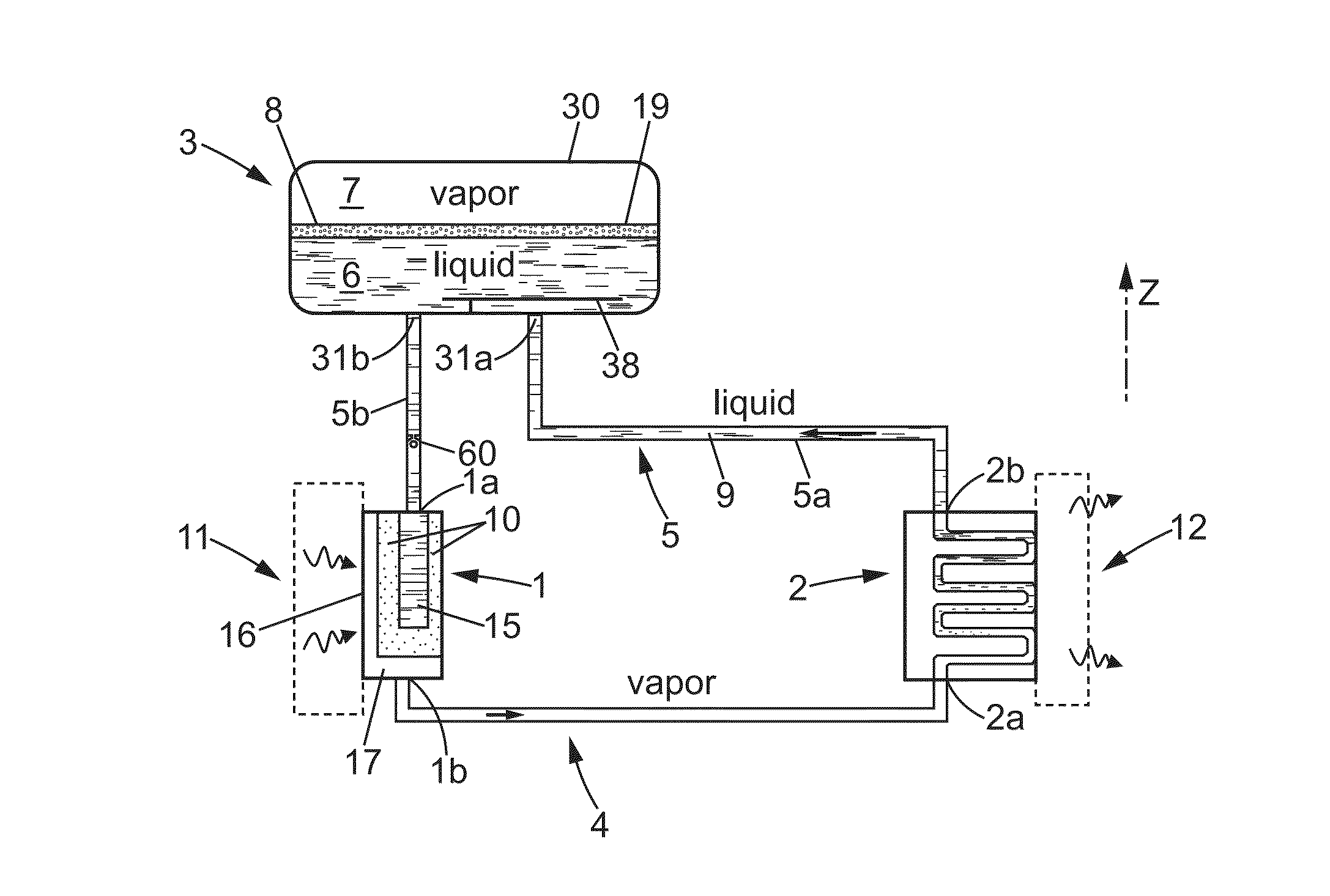
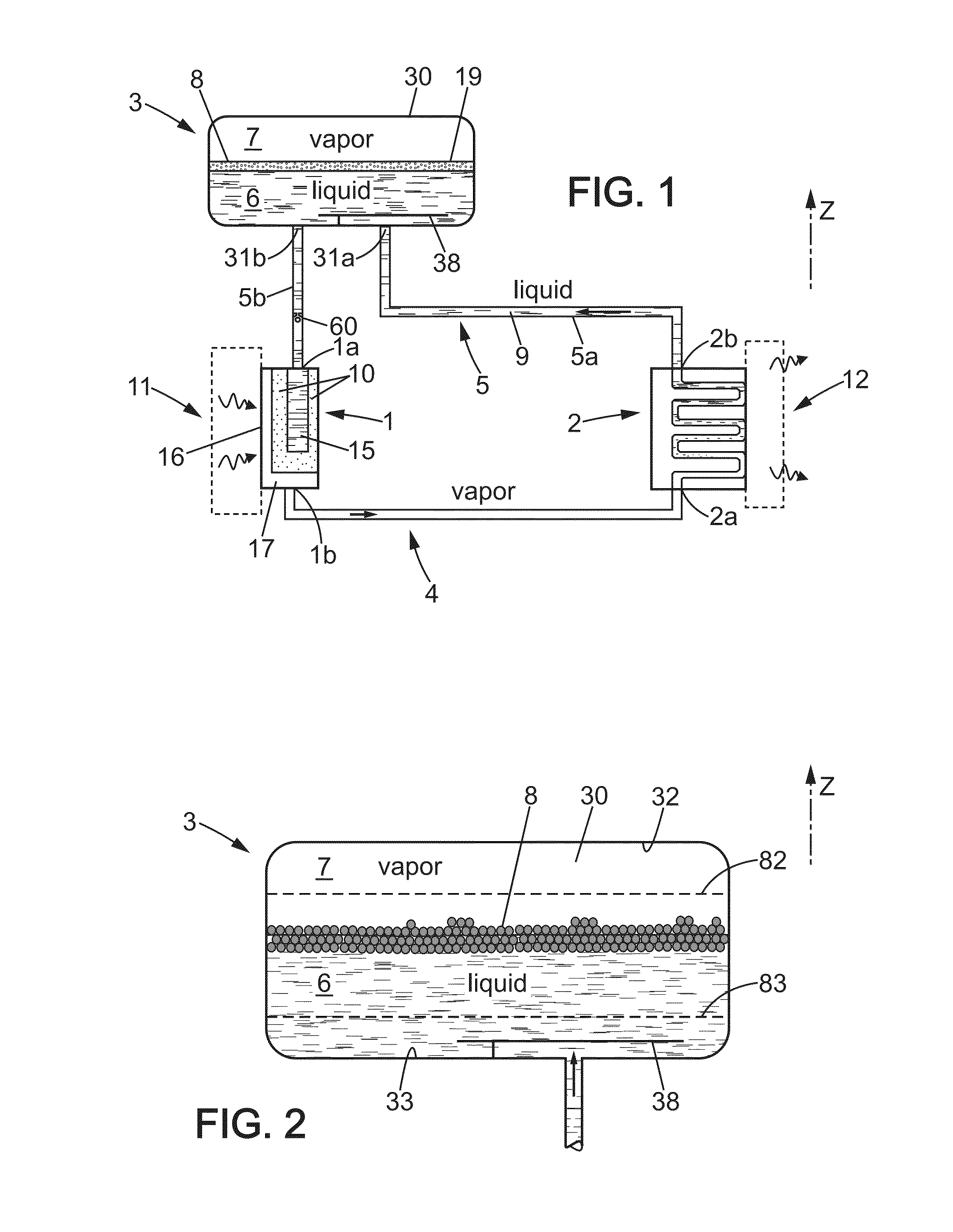
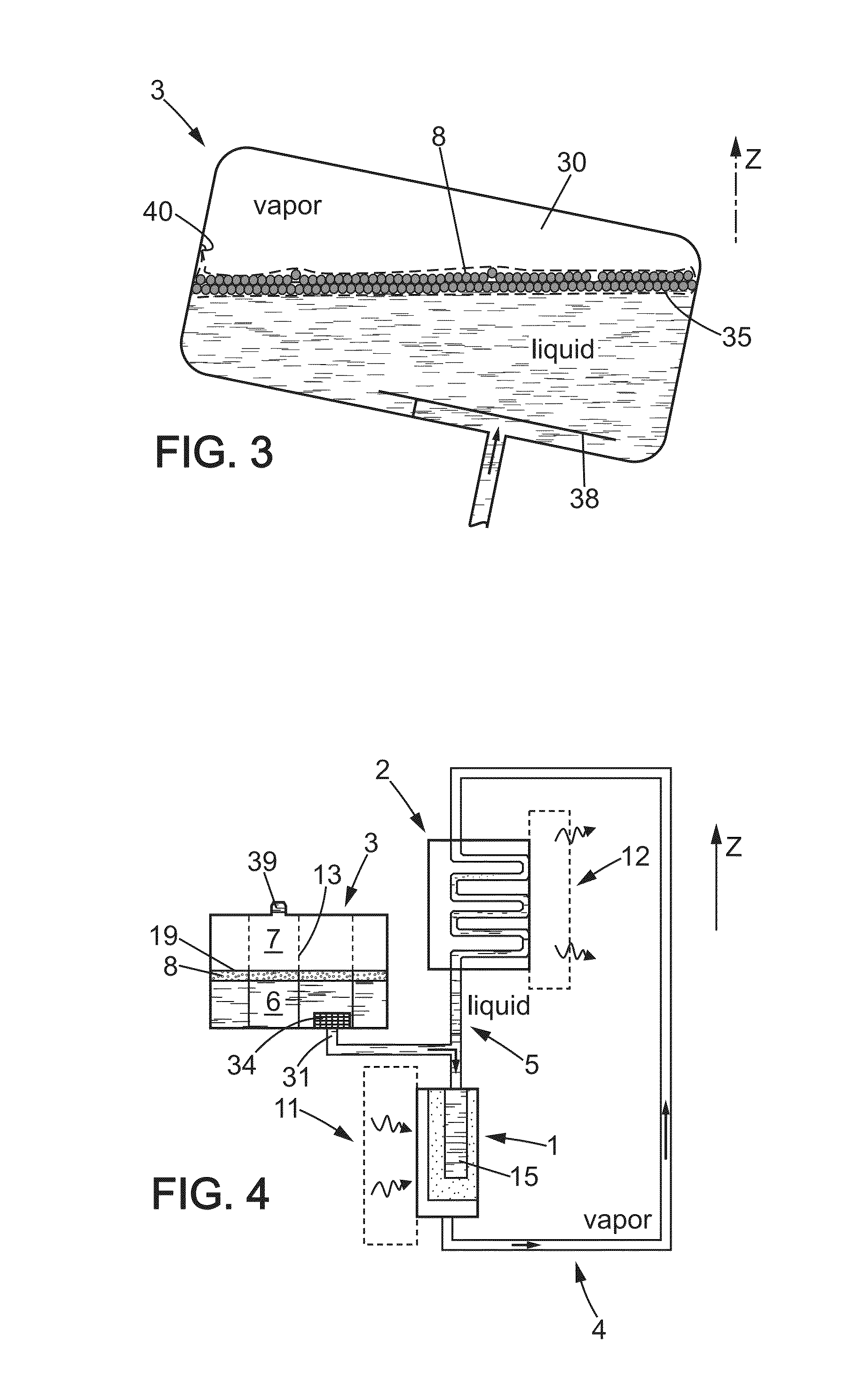
[0040]FIG. 1 shows a capillary-driven heat transfer device, with a two-phase fluid loop. The device comprises an evaporator 1, having an inlet 1a and an outlet 1b, and a microporous mass 10 suitable for performing capillary pumping. For this purpose, the microporous mass 10 surrounds a blind central longitudinal recess 15 communicating with the inlet 1a in order to receive working fluid 9 in a liquid state from a reservoir 3.

[0041]The evaporator 1 is thermally coupled with a heat source 11, such as for example an assembly comprising electronic power components or any other component generating heat, by Joule effect for example, or by any other method.

[0042]Under the effect of the contribution of calories at the contact 16 with the microporous mass filled with liquid, fluid passes from the liquid state to the vapor state and is evacuated through the transfer chamber 17 and through a first communication circuit 4 which conveys said vapor to a condenser 2 which has an inlet 2a and an o...


PUM


Abstract

A two-phase heat transfer device that is capillary-driven or gravity-driven, has a two-phase working fluid contained in a closed general circuit, including an evaporator, a condenser, a reservoir having an inner volume with a liquid portion and a gas portion, a first vapor communication circuit, and a second liquid phase communication circuit. The reservoir comprises a plurality of floating bodies separating the liquid portion from the gas portion, by means of which the heat exchanges between the liquid portion and the gas portion are slowed down, which allows to diminish the effect of movement of the liquid portion or of an influx of cold or warm liquid into the reservoir.

Description

BACKGROUND[0001]1. Technical Field[0002]The present invention relates to two-phase heat transfer devices, in particular mechanically passive devices with a two-phase fluid loop that are capillary-driven or gravity-driven.[0003]2. Description of the Related Art[0004]It is known from document FR-A-2949642 that such devices are used as cooling means for electrotechnical power converters.[0005]These devices can be temperature-controlled by controlling the pressure in the reservoir. This control can be active (electric heating resistor) or entirely passive (introduction of an auxiliary gas into the reservoir).[0006]However, it has appeared that the startup phases were particularly subject to problems for high thermal power levels, drying-out of the capillary wick can occur resulting in a startup failure.[0007]Moreover, if the device is subjected to accelerations, a phenomenon known as ‘cold shock’ may occur in the reservoir which suddenly lowers the pressure and degrades performance.[000...

Claims


Application Information

Patent Timeline
IPC IPC(8): F28D15/02F25B23/00F28D15/04
CPCF28D15/025F25B23/00F28D15/043F25B23/006B60H1/00492B60H1/3202F28F2265/12
Inventor DUPONT, VINCENT
Owner EURO HEAT PIPES
Learn More