Visual field calculation apparatus and method for calculating visual field

Active Publication Date: 2016-05-05
PANASONIC INTELLECTUAL PROPERTY MANAGEMENT CO LTD
View PDF2 Cites 20 Cited by
  • Summary
  • Abstract
  • Description
  • Claims
  • Application Information

AI Technical Summary

Benefits of technology

[0008]According to the visual field calculation apparatus according to the present

Problems solved by technology

In the method of Japanese Unexamined Patent Application Publication No. 2011-206072, however, means (e.g., a device such as a camera) for detecting a mov

Method used


Image

  • Visual field calculation apparatus and method for calculating visual field
  • Visual field calculation apparatus and method for calculating visual field
  • Visual field calculation apparatus and method for calculating visual field

Examples


first embodiment

[0041]The first embodiment of the present disclosure will be described.

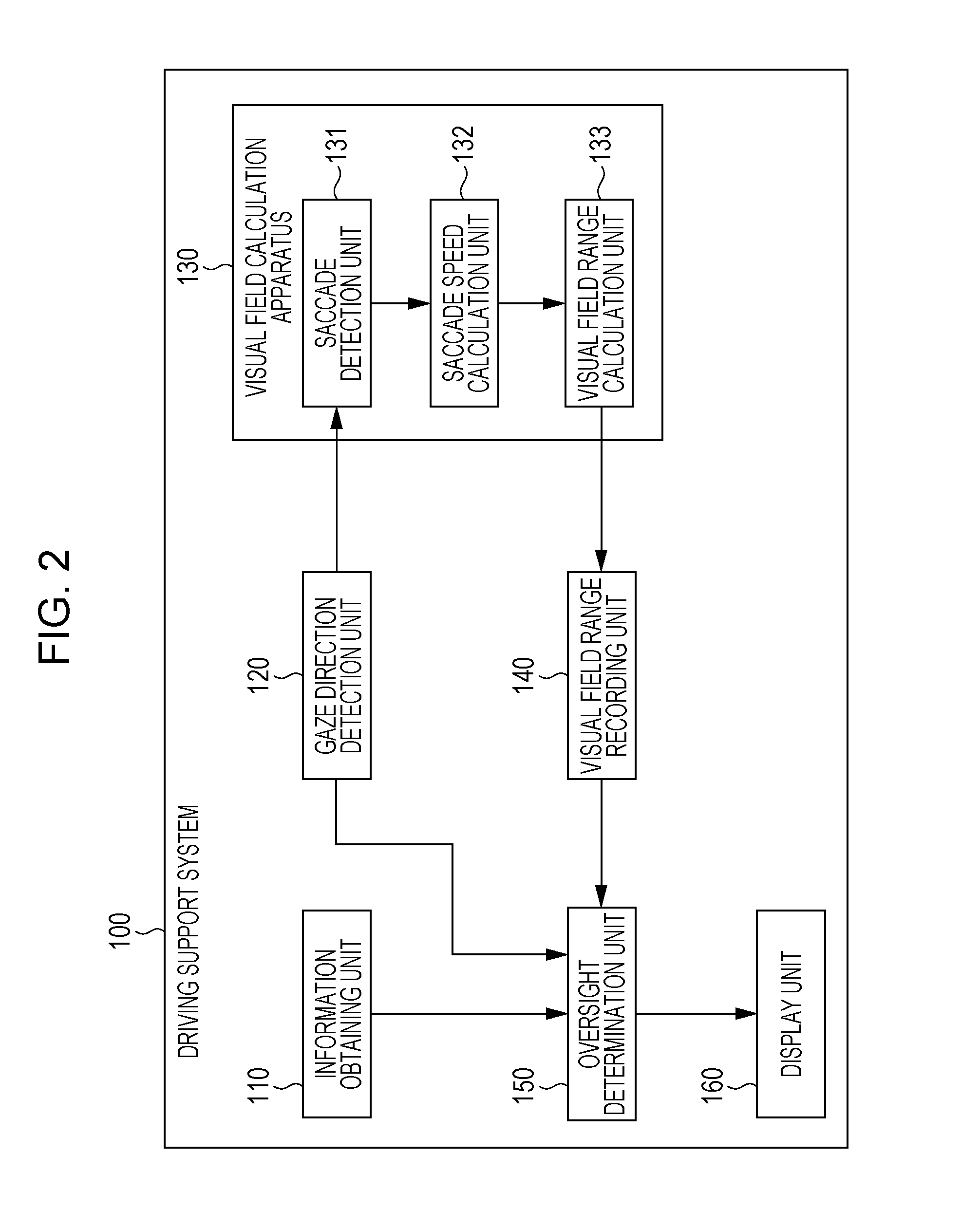
[0042]FIG. 2 is a block diagram illustrating an example of the configuration of a driving support system 100 including a visual field calculation apparatus 130 according to the present embodiment. In FIG. 2, the driving support system 100 includes an information obtaining unit 110, a gaze direction detection unit 120, the visual field calculation apparatus 130, a visual field range recording unit 140, an oversight determination unit 150, and a display unit 160.

[0043]The driving support system 100 is a system that is mounted on a vehicle such as an automobile, detects an obstacle around the vehicle missed by the user, and issues an alarm, a warning, or the like to the user using at least either auditory means or visual means. As a result, it is possible to prevent the user from missing an obstacle around the vehicle and support safe driving. It is to be noted that the “user” in the first to fourth embodiments refe...

second embodiment

[0095]The second embodiment of the present disclosure will be described.

[0096]FIG. 13 is a block diagram illustrating an example of the configuration of a driving support system 100 including a visual field calculation apparatus 130 according to the present embodiment. The configuration illustrated in FIG. 13 is different from the configuration according to the first embodiment (FIG. 2) in that the visual field calculation apparatus 130 includes a visual field calculation time setting unit 135. In FIG. 13, the same components as those illustrated in FIG. 2 are given the same reference numerals. Only differences from the configuration illustrated in FIG. 1 will be described hereinafter.

[0097]The visual field calculation time setting unit 135 sets the saccade detection period T3 as a time used for calculating the visual field by estimating a point in time when the visual field range is assumed to have changed.

Operation for Calculating Visual Field

[0098]Next, an example of the operatio...

third embodiment

[0104]The third embodiment of the present disclosure will be described.

[0105]FIG. 16 is a block diagram illustrating an example of the configuration of a driving support system 100 including a visual field calculation apparatus 130 according to the present embodiment. The configuration illustrated in FIG. 16 is different from the configuration according to the first embodiment (FIG. 2) in that the visual field calculation apparatus 130 includes a face direction detection unit 136 and the driving support system 100 includes a vehicle information obtaining unit 170 and a navigation information obtaining unit 180. In FIG. 16, the same components as those illustrated in FIG. 2 are given the same reference numerals. Only differences from the configuration according to the first embodiment will be described hereinafter.

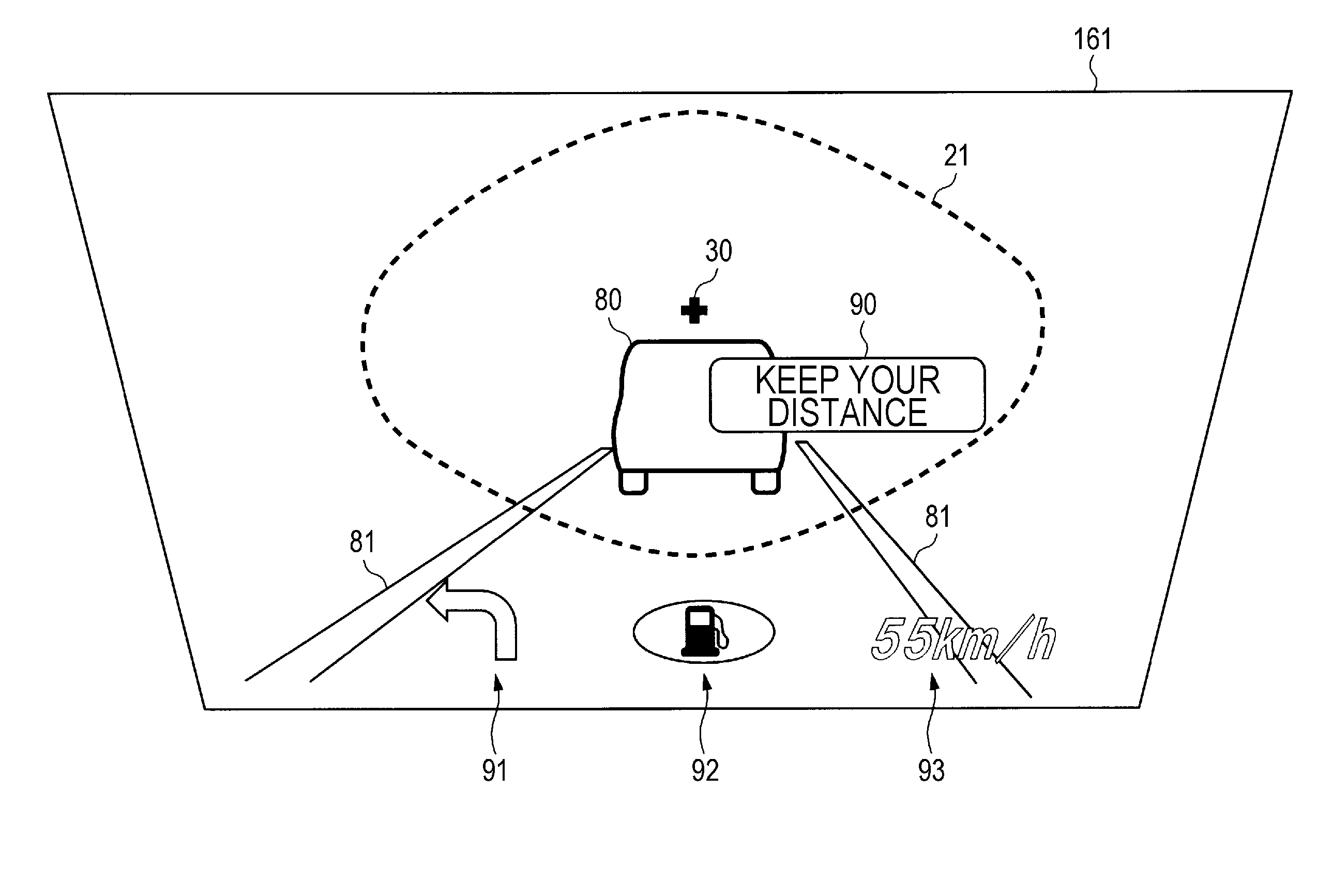
[0106]The driving support system 100 is a system that displays vehicle information and navigation information (both of which will be described later) on a head-up display a...


PUM


Abstract

A visual field calculation apparatus capable of accurately calculating a visual field range of a user without using a complex configuration is provided. The visual field calculation apparatus includes a saccade detector that detects a saccade on the basis of a first gaze direction detected at a first timing and a second gaze direction detected at a second timing, a saccade speed calculator that calculates speed of the saccade on the basis of a time difference between the first timing and the second timing, the first gaze direction, and the second gaze direction, and a visual field range calculator that calculates a displacement vector of a saccade whose speed exceeds a first threshold, and calculates an area including a final point of the displacement vector as the visual field range of the user.

Description

BACKGROUND[0001]1. Technical Field[0002]The present disclosure relates to a visual field calculation apparatus and a method for calculating a visual field.[0003]2. Description of the Related Art[0004]As a method for calculating a visual field range (also referred to as a “visual field area”) of a user who is driving a vehicle, a method disclosed in Japanese Unexamined Patent Application Publication No. 2011-206072, for example, is currently known. In the method described in Japanese Unexamined Patent Application Publication No. 2011-206072, a moving object (e.g., a person) outside a vehicle is detected using means for detecting a moving object outside the vehicle, and a gaze direction of the user is measured using means for detecting a gaze direction of the user. If it is determined on the basis of the moving object and the gaze direction that the user is gazing at a moving object outside the vehicle, the visual field range is calculated on the basis of the position of a gaze point....

Claims


Application Information

Patent Timeline
IPC IPC(8): A61B3/113A61B5/00G02B27/01A61B3/00
CPCA61B3/113A61B3/0025G02B27/0101A61B5/6893A61B3/0041A61B3/024G02B2027/0187G02B27/01G02B2027/0123G08G1/162G08G1/166G06F3/013A61B5/398G06V40/19G06F3/01
Inventor MOCHIZUKI, MAKOTOEMURA, KOICHIMATSUSE, TETSUOITO, HAYASHI
Owner PANASONIC INTELLECTUAL PROPERTY MANAGEMENT CO LTD
Why Eureka
Try Eureka