
A disc filter apparatus

Inactive Publication Date: 2016-05-05
OUTOTEC FINDLAND OY
View PDF0 Cites 4 Cited by
  • Summary
  • Abstract
  • Description
  • Claims
  • Application Information

AI Technical Summary

Benefits of technology

The disc filter apparatus described in this patent allows for easy adjustment of the position of individual filter plates in the axial direction, which is important for achieving consistent and efficient filtration. The adjustment is made possible through use of an adjustable sleeve construction, which allows for precise positioning of the filter plate in relation to the rim structure. This design also reduces the requirements for the planarity of the rim structure, as the filter plates can be positioned in the same radial plane regardless of any unevenness in the surface of the rim structure. Additionally, the position of the outer surface of the adjustable sleeves can be easily adjusted through use of a laser beam or a 3D laser planarity measurement device. These features make the disc filter apparatus more robust and reliable, while also improving its performance and efficiency.

Problems solved by technology

Pressure filters often operate in batch mode because continuous cake discharge is more difficult to achieve.
This solution is costly as it requires a set of special machinery and skills.

Method used


Image

  • A disc filter apparatus
  • A disc filter apparatus
  • A disc filter apparatus

Examples


Embodiment Construction

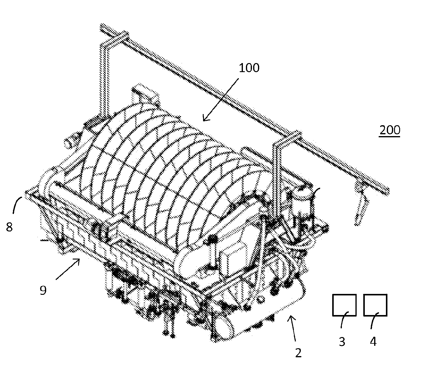
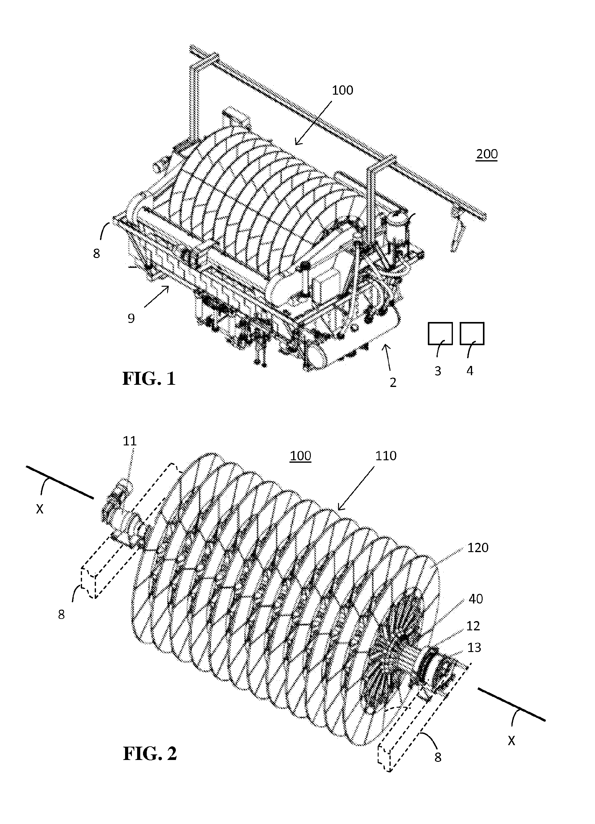
[0024]FIG. 1 is a perspective top view of a disc filter apparatus, wherein the invention may be applied. FIG. 2 is a perspective top view of the drum of FIG. 1.

[0025]The disc filter apparatus 200 comprises a cylindrical-shaped drum 100 that is supported by bearings 11 and 12 on a frame 8. The drum 100 is rotatable about a longitudial centre axis X-X such that a lower portion of the drum 100 is submerged in a slurry basin 9 located below the centre axis X-X. The drum 100 is rotated by a motor e.g. an electric motor through a gear box. The drum 100 comprises a plurality of ceramic filter discs 110 arranged in line co-axially around the centre axis X-X of the drum 100. The number of the ceramic filter discs 110 on the drum 100 may be in the range of 2 to 20. The diameter of each disc 110 may be in the range of 1.5 to 4 m.

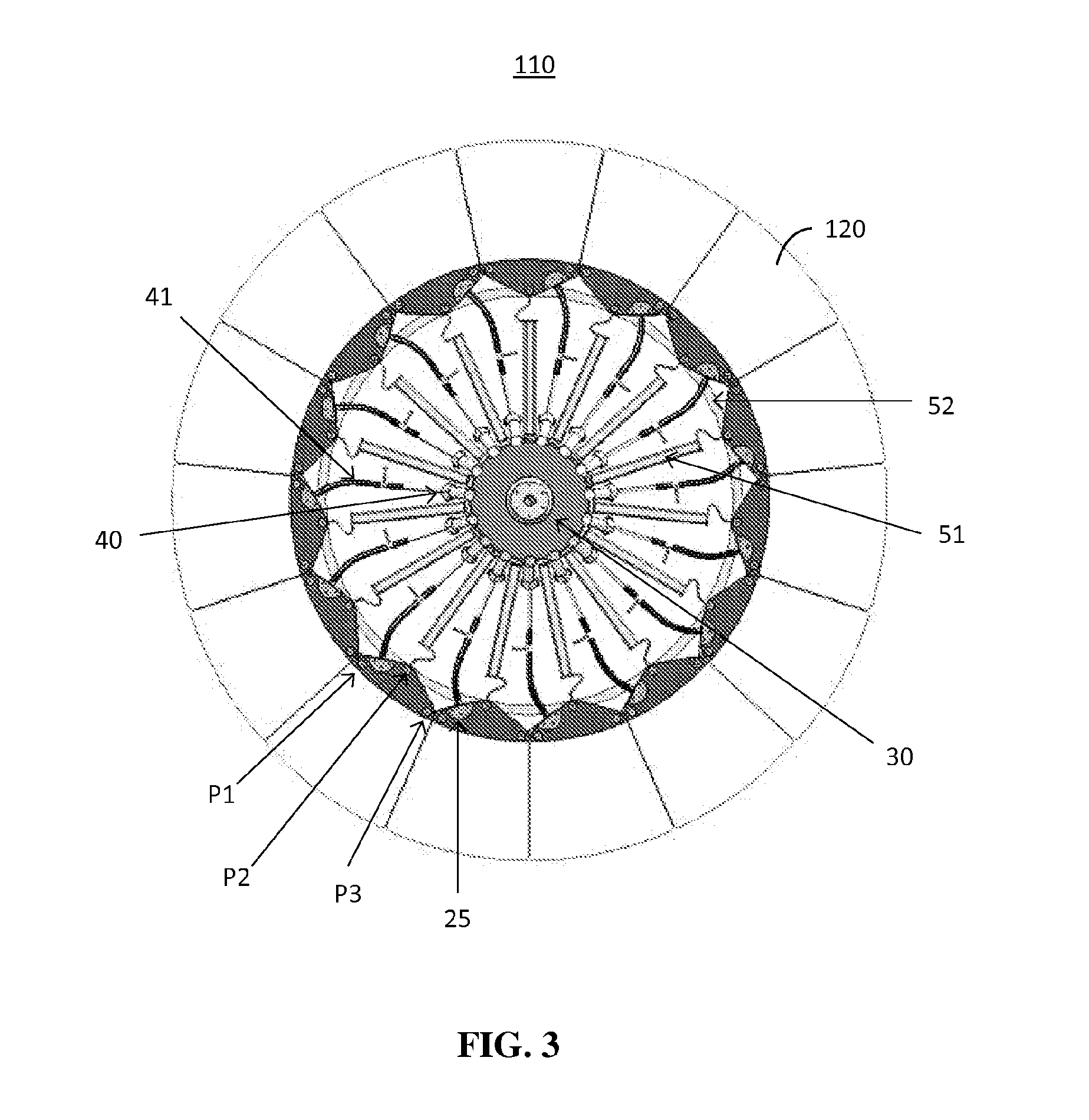
[0026]FIG. 3 is a radial cross section of one filter disc of the drum in FIG. 2. FIG. 4 is a perspective view of a filter plate in the filter disc in FIG. 3.

[0027]FIG....


PUM

PropertyMeasurementUnit
Distanceaaaaaaaaaa

Abstract

The disc filter apparatus comprises a drum that is rotatable around a shaft having a centre axis. The drum comprises filter discs positioned at an axial distance from each other. Each filter disc comprises a rim structure supported on the shaft and truncated, sector shaped filter plates mounted circumferentially in a radial plane to form an essentially continuous and planar disc surface. Each filter plate is attached with a fastening arrangement to the rim structure from a lower edge portion of the filter plate through at least three fastening points. The fastening arrangement between the filter plate and the rim structure comprises at each fastening point in the rim structure an adjustable sleeve construction. Prior art solutions require a radially planar fastening surface in the rim structure in order to have all the filter plates in one filter disc in the same radial plane. This is not necessary in the invention due to the use of an adjustable sleeve construction.

Description

FIELD OF THE INVENTION[0001]The present invention relates to a disc filter apparatus according to the preamble of claim 1.BACKGROUND OF THE INVENTION[0002]Filtration is a widely used process whereby a slurry or solid liquid mixture is forced through a media, with the solids retained on the media and the liquid phase passing through. Examples of filtration types include depth filtration, pressure and vacuum filtration, and gravity and centrifugal filtration.[0003]Both pressure and vacuum filters are used in the dewatering of mineral concentrates. Pressure filtration is based on the generation of an overpressure within a filtration chamber. Consequently, solids are deposited onto the surface of the filter medium and filtrate flows through the filter medium into the filtrate channels. Pressure filters often operate in batch mode because continuous cake discharge is more difficult to achieve.[0004]Vacuum filtration is based on producing a suction within the filtrate channels and thereby...

Claims


Application Information

Patent Timeline
IPC IPC(8): B01D33/23B01D33/80
CPCB01D33/803B01D33/23B01D33/21
Inventor YLISIURUA, HANNU
Owner OUTOTEC FINDLAND OY
Learn More