Repair method and device for the additive repair of a component

a technology for repair methods and components, applied in the field of repair methods for components, can solve the problems of limited removal as much as possible to the damaged region of the component, and achieve the effects of simple way, rapid, precise and contact-free determination, and convenient alignment or adjustment of the actual geometry

Inactive Publication Date: 2016-05-05
MTU AERO ENGINES GMBH
View PDF3 Cites 27 Cited by
  • Summary
  • Abstract
  • Description
  • Claims
  • Application Information

AI Technical Summary

Benefits of technology

[0022]Additional advantages result if the device comprises a retaining device, by means of which the component can be fixed in place in a predetermined spatial orientation in the processing chamber. The locally fixed arrangement of the component relative to the processing chamber, in particular, facilitates the alignment or adjustment of the actual geometry and the target geometry.
[0023]Additional advantages result if the measurement system is designed as an optical measurement system. This permits a rapid, precise, and contact-free determination of the actual geometry of the component. For example, the measurement system can be designed as a stripe projection system. This can be integrated into the device in a particularly simple way.

Problems solved by technology

Preferably, this step is carried out in such a way that the removal is limited as much as possible to the damaged region of the component.

Method used


Image

  • Repair method and device for the additive repair of a component
  • Repair method and device for the additive repair of a component
  • Repair method and device for the additive repair of a component

Examples


Embodiment Construction

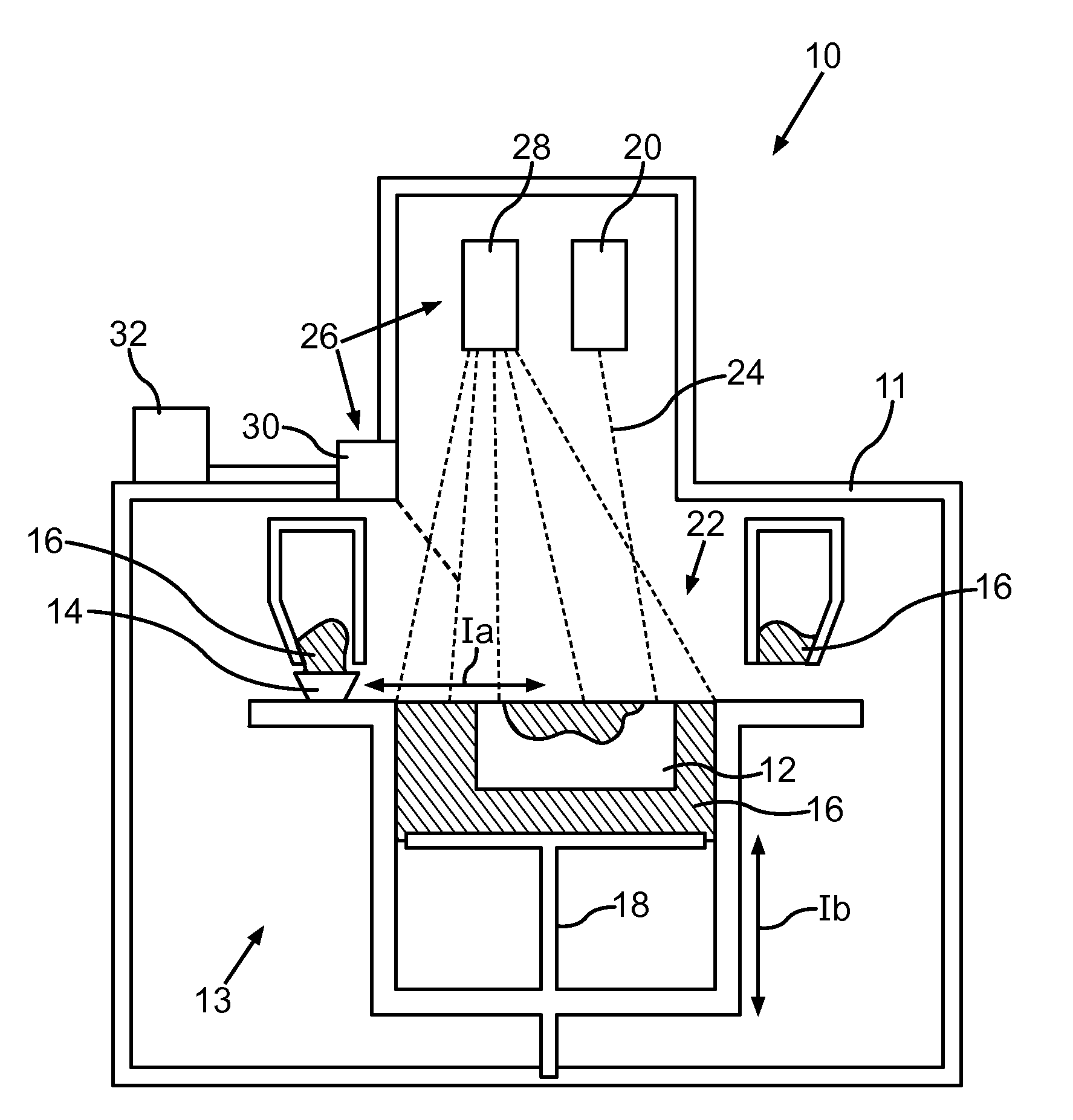
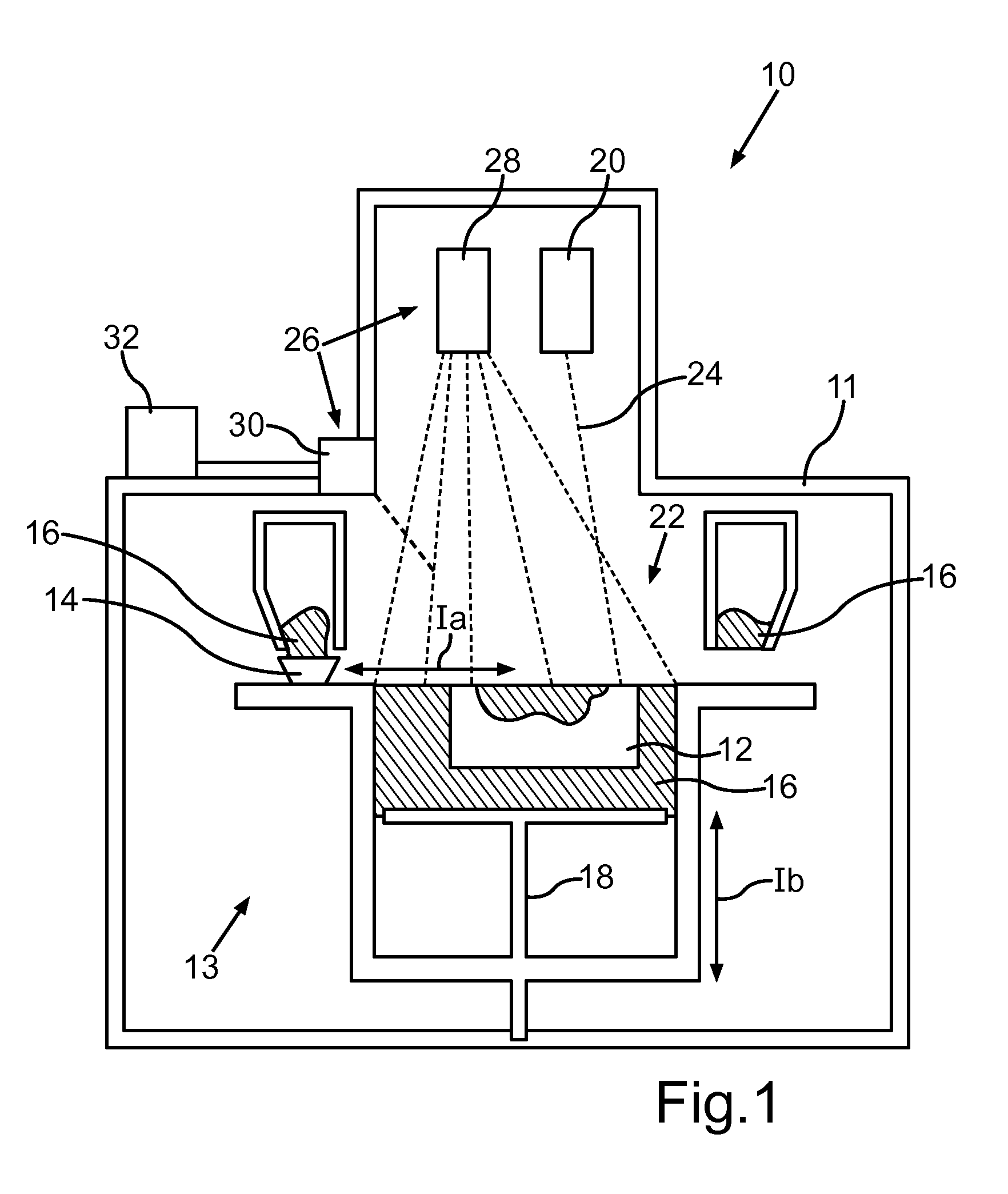
[0027]FIG. 1 shows a schematic sectional view of an exemplary embodiment of a device 10 according to the invention for the additive repair of a component 12, which is designed presently as a rotating blade of a turbine of an aircraft engine. The device 10 comprises a processing chamber 11, in which construction means 13 for the additive restoration of a region of the component 12 is found. The construction means 13 in the present exemplary embodiment comprises a powder supply 14 that can move according to double arrow Ia for the allocation of at least one powder-form component material 16, this supply found on a component platform 18 that can move according to double arrow Ib. In addition, a high-energy source 20 presently designed as a laser is provided, by means of which a laser beam or pulsed laser 24 is generated in the region of a construction and joining zone 22 of the component platform 18 for a layerwise and local melting and / or sintering of the component material 16. Equipm...


PUM

PropertyMeasurementUnit
energyaaaaaaaaaa
optical measurementaaaaaaaaaa
volumeaaaaaaaaaa

Abstract

The invention relates to a repair method for a component (12) and includes the steps of removal of a damaged region of the component (12) with the formation of at least one separating surface; arrangement of the component (12) in a processing chamber (11) of a device (10) for the additive restoration of at least the region of the component that has been removed; determining first structural data of the component (12) disposed in the processing chamber (11); providing second structural data of the component (12); determining third structural data based on the first and the second structural data; and additive restoration of the component region that has been removed on the at least one separating surface of the component (12). In addition, the invention relates to a device (10) for the additive repair of a component (12).

Description

BACKGROUND OF THE INVENTION[0001]The invention relates to a repair method for a component, in particular for a blade or vane of a gas turbine. In addition, the invention relates to a device for the additive repair of a component.[0002]For the repair of worn or damaged components by means of additive repair methods, the individual recording of the exact actual geometric data based on the individual shape and damage of each component and a time-consuming adjustment of the target geometric data that are usually present as a CAD model are necessary. Subsequently, for the additive restoration of the damaged region of the component, the position, location and contour of the component surfaces to be worked in the processing space or construction space of the device employed must be defined precisely.[0003]A repair method in which damaged turbine components are first cut back to a predetermined geometry is known from US 2012 / 0222306 A1. Subsequently, the component is inserted into a process...

Claims


Application Information

Patent Timeline
Patent Type & Authority Applications(United States)
IPC IPC(8): B23P6/00
CPCB23P6/00B22F5/04B23P6/007F01D5/005B22F2007/068F05D2230/31Y10T29/49318Y10T29/49723B33Y50/02Y02P10/25B22F10/62B22F12/43B22F10/66B22F12/90B22F10/80B22F10/28B23P6/002
Inventor LADEWIG, ALEXANDERSCHLOTHAUER, STEFFENHESS, THOMASLIEBL, CHRISTIAN
Owner MTU AERO ENGINES GMBH
Why Eureka
Try Eureka