Eureka AIR delivers breakthrough ideas for toughest innovation challenges, trusted by R&D personnel around the world.

Methods and system for fluidic sealing in gas turbine engines

Active Publication Date: 2016-05-05
GENERAL ELECTRIC CO
View PDF4 Cites 0 Cited by
  • Summary
  • Abstract
  • Description
  • Claims
  • Application Information

AI Technical Summary

Benefits of technology

The patent text describes a sealing system for a rotating element that is designed to channel the flow of a combustion gas and a heat transfer medium separately. The sealing system includes a rotor blade and a stator vane with a clearance gap between them. The sealing mechanism includes an obliquely oriented surface that helps to create a converging nozzle, which improves sealing efficiency. The technical effects of this invention are to provide a more reliable and efficient sealing system for rotating elements, which can help to improve the performance and efficiency of combustion turbines and other industrial equipment.

Problems solved by technology

However, the channeling of cooling air into the inner wheelspace may have the effect of reducing engine efficiency.
Furthermore, the size of the gap defined between the stator platform and the angel wing must accommodate transient events in the engine due to rotation of the rotor and expansion of certain turbine components due to heat.
The gap is large enough to provide a path which can allow hot combustion gases into the wheelspace and, therefore, requires an amount of the cooling air that may negatively affect engine efficiency.

Method used


Image

  • Methods and system for fluidic sealing in gas turbine engines
  • Methods and system for fluidic sealing in gas turbine engines
  • Methods and system for fluidic sealing in gas turbine engines

Examples


Embodiment Construction

[0021]In the following specification and the claims, reference will be made to a number of terms, which shall be defined to have the following meanings.

[0022]The singular forms “a”, “an”, and “the” include plural references unless the context clearly dictates otherwise.

[0023]Approximating language, as used herein throughout the specification and claims, is applied to modify any quantitative representation that could permissibly vary without resulting in a change in the basic function to which it is related. Accordingly, a value modified by a term or terms, such as “about”, “approximately”, and “substantially”, are not to be limited to the precise value specified. In at least some instances, the approximating language may correspond to the precision of an instrument for measuring the value. Here and throughout the specification and claims, range limitations are combined and interchanged; such ranges are identified and include all the sub-ranges contained therein unless context or lan...


PUM


Abstract

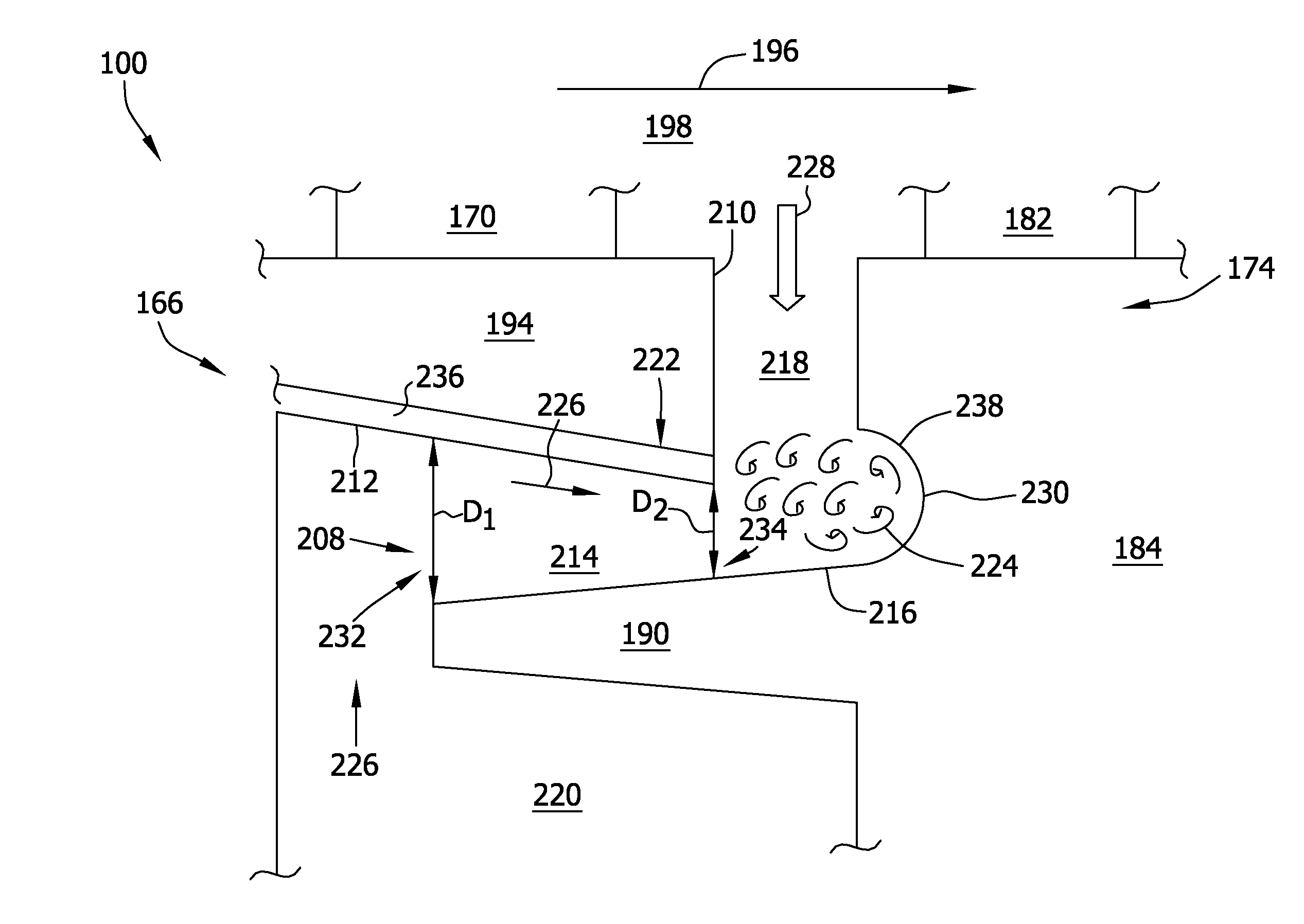
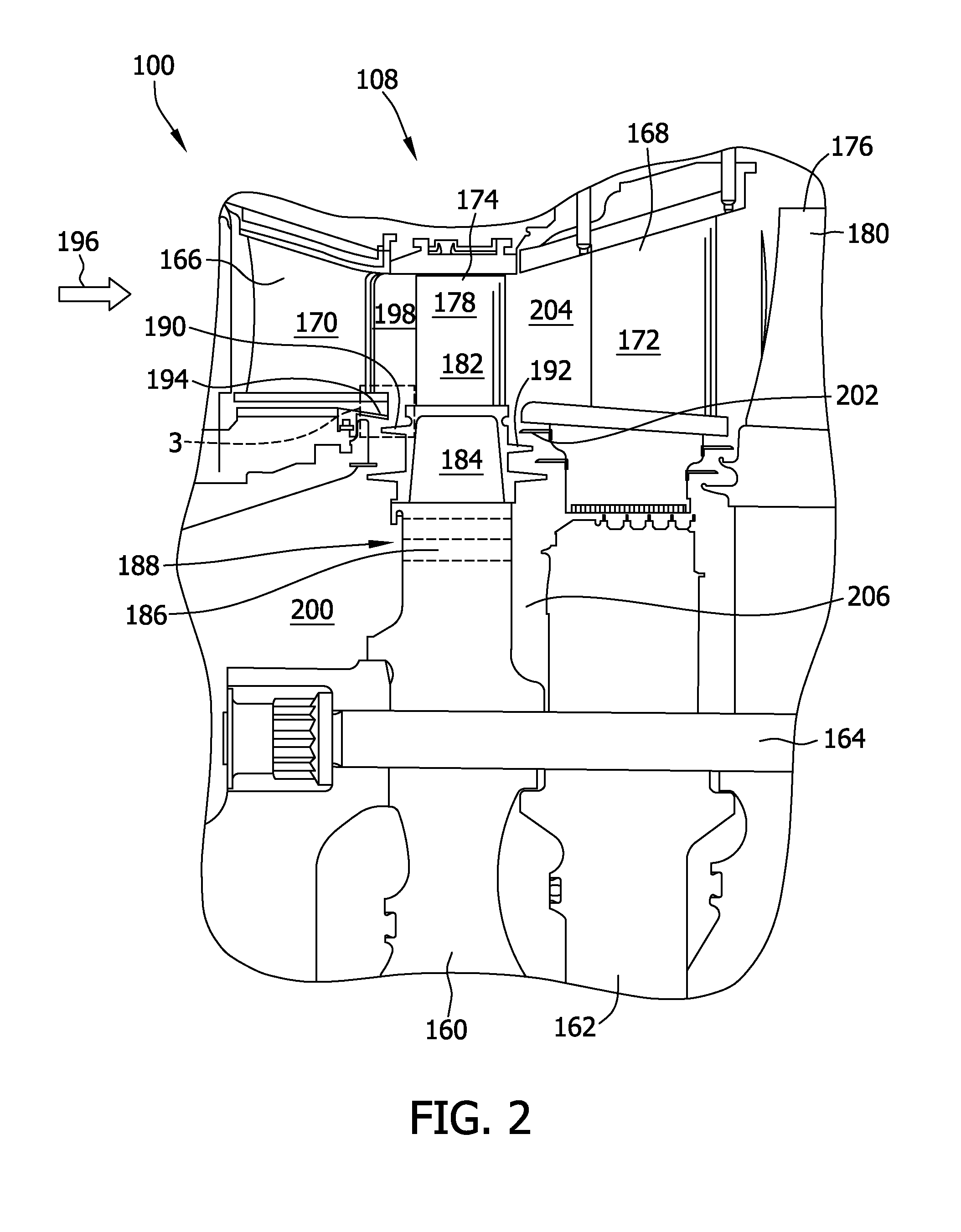
A sealing system for a rotatable element defining an axis of rotation includes a rotor blade including a shank and an angel wing extending axially from the shank. The sealing system also includes a stator vane positioned axially adjacent the rotor blade. The stator vane includes a platform extending in an axial direction over the angel wing such that a clearance gap is defined therebetween. The sealing system also includes a sealing mechanism including a portion of the platform and a portion of the angel wing. The sealing mechanism includes at least one obliquely oriented surface such that the clearance gap defines a converging nozzle.

Description

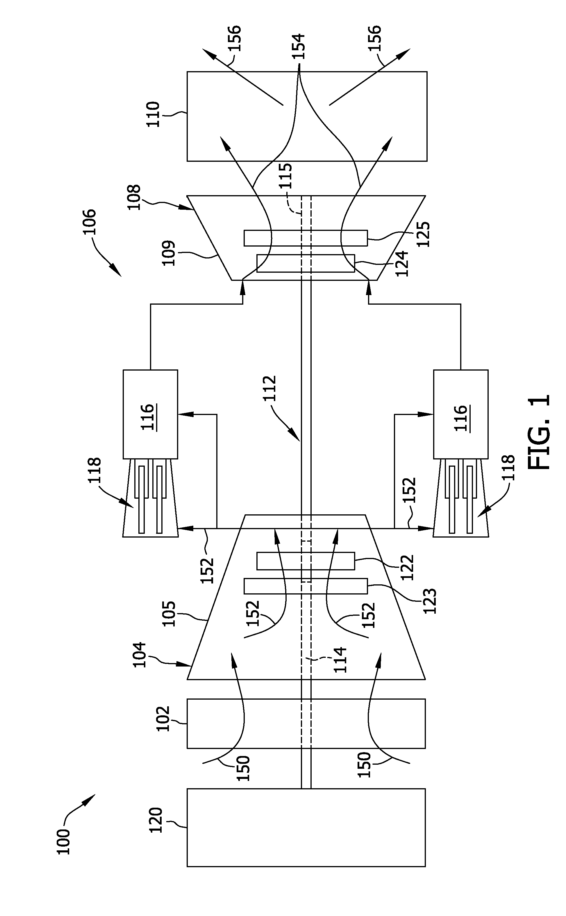
BACKGROUND[0001]This invention relates generally to turbomachines. More specifically, the invention is directed to methods and apparatus for impeding the flow of gas (e.g., hot gas) through selected regions of stator-rotor assemblies in turbomachines, such as turbine engines.[0002]In operation of at least some known turbine engines, intake air is channeled towards a compressor where it is compressed to higher pressures and temperatures prior to being discharged towards a combustor section. The compressed air is channeled to a fuel nozzle assembly, mixed with fuel, and burned within each combustor to generate combustion gases that are channeled downstream through a rotor / stator cavity of a turbine section. The combustion gases impinge upon rotor blades positioned within the turbine to convert thermal energy into mechanical rotational energy that is used to drive a rotor assembly. The turbine section drives the compressor section and / or a load, via separate drive shafts, and discharge...

Claims


Application Information

Patent Timeline
IPC IPC(8): F01D11/00F01D25/12F01D11/02
CPCF01D11/001F01D25/12F01D11/02F05D2250/294
Inventor RUGGIERO, ERIC JOHNRODEBAUGH, GREGORY PAULMIORINI, RINALDO LUIGI
Owner GENERAL ELECTRIC CO
Why Eureka
Eureka Blog
Learn More