Blind body positioning mechanism for non pull cord window blind and window blind using same

Active Publication Date: 2016-05-05
CHEN CHIN FU
View PDF0 Cites 16 Cited by
  • Summary
  • Abstract
  • Description
  • Claims
  • Application Information

AI Technical Summary

Benefits of technology

The present invention is a blind body positioning mechanism for non pull cord window blinds that has a simple structure and provides excellent positioning effects, enhancing operating convenience. The mechanism has resistance wheels and transmission cords that work together to achieve excellent positioning effects. Each resistance unit also has a resistance shrapnel that improves the resistance effect. The non pull cord window blind also includes a top rail, bottom rail, and blind body positioning mechanism that synchronously moves the bottom rail with the two transmission cords.

Problems solved by technology

However, although a non pull cord blind allows users to easily extend out or receive the blind body, the blind body is prone to rebounding after fully extended out, or sagging after fully received due to lack of good positioning design in the structural configuration, bringing trouble to the user in actual operation.

Method used


Image

  • Blind body positioning mechanism for non pull cord window blind and window blind using same
  • Blind body positioning mechanism for non pull cord window blind and window blind using same
  • Blind body positioning mechanism for non pull cord window blind and window blind using same

Examples


Embodiment Construction

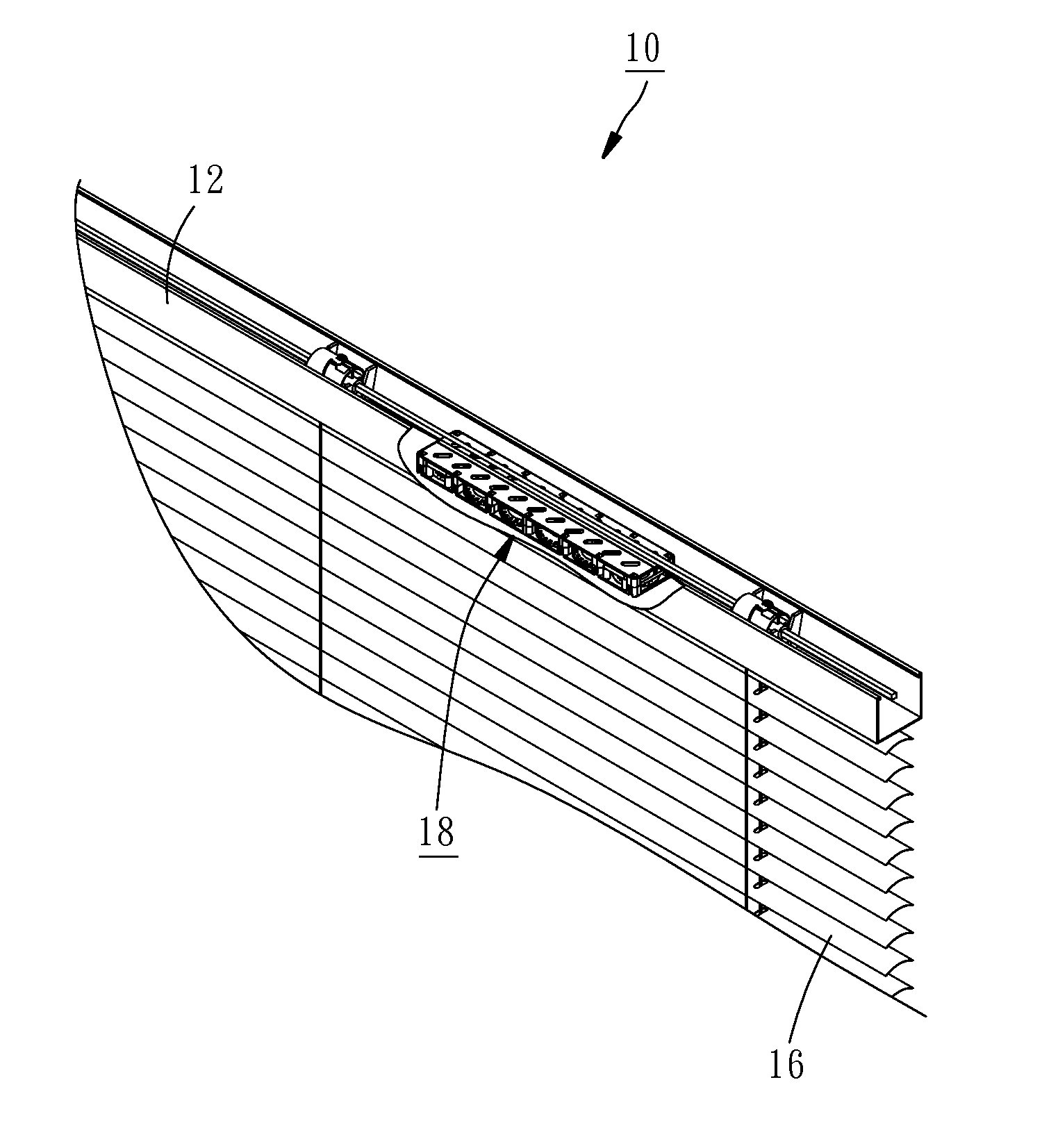
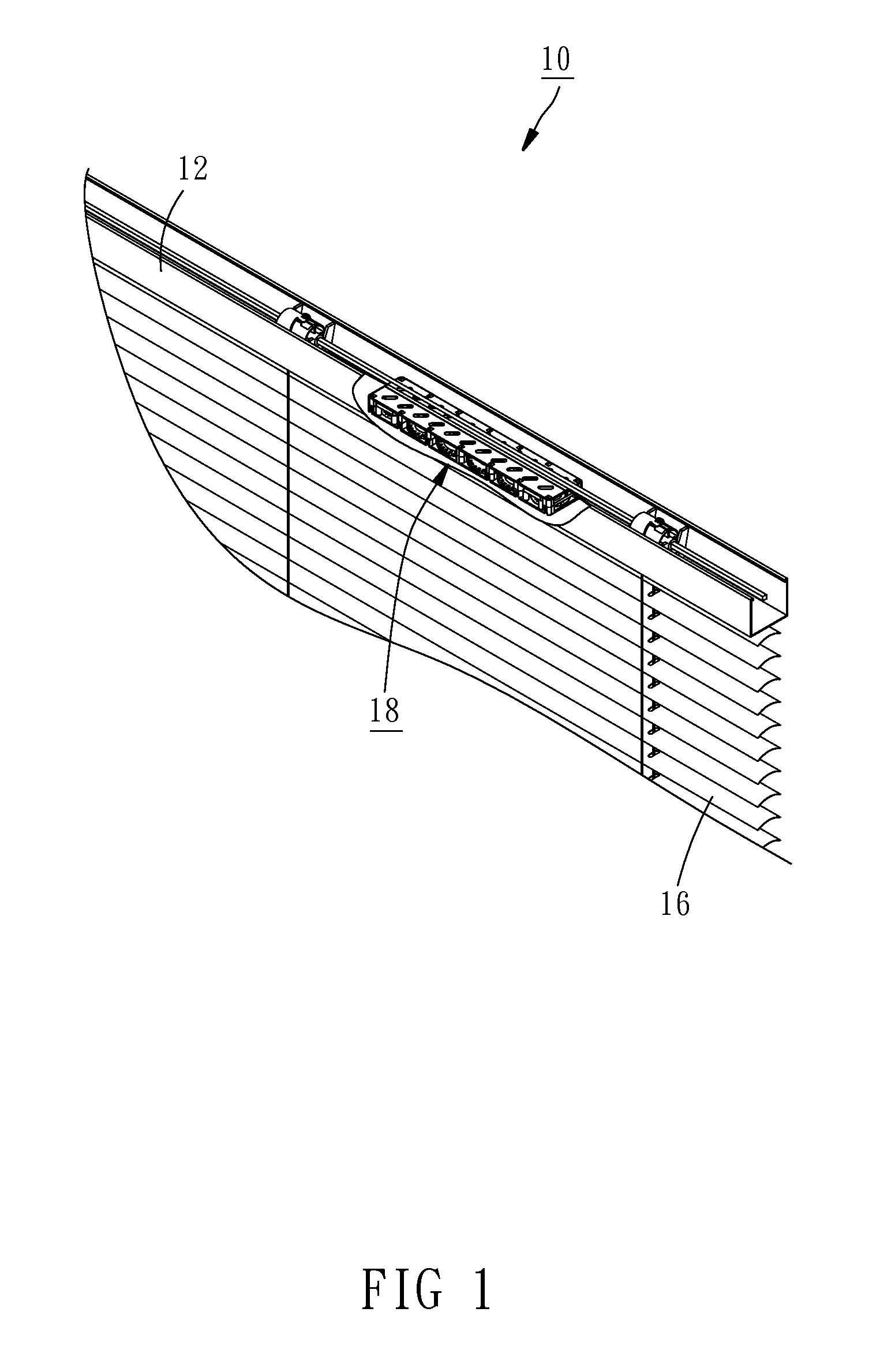
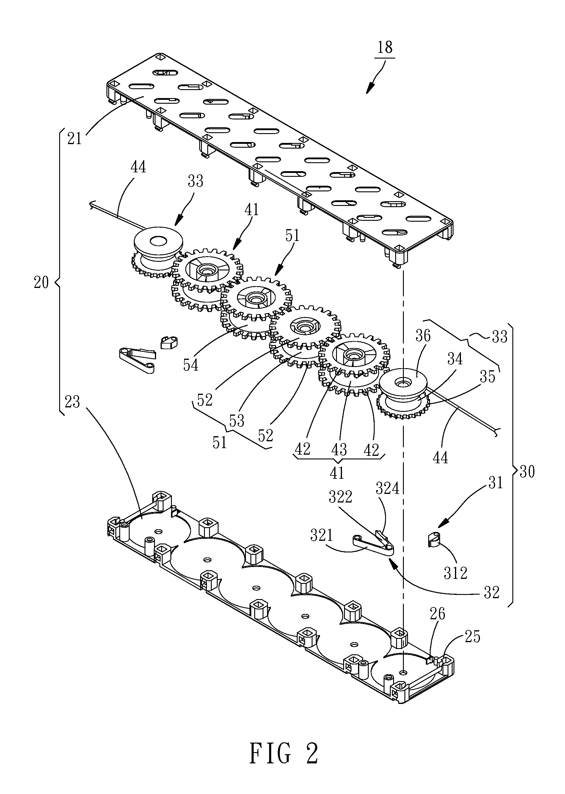
[0019]Referring to FIGS. 1 and 4, a non pull cord window blind 10 in accordance with the present invention is shown. As illustrated, the non pull cord window blind 10 comprises a top rail 12, an opposing bottom rail 14, and blind body 16 coupled between the top rail 12 and the bottom rail 14. Referring to FIG. 2, a blind body positioning mechanism 18 in accordance with a first embodiment of the present invention comprises a casing 20, two resistance units 30, two first transmission wheels 41, two transmission cords 44, two second transmission wheels 51, and a coil spring 54.

[0020]The casing 20 is mounted inside the top rail 12, comprising a top locating plate 21 and a bottom locating plate 23. The top locating plate 21 and the bottom locating plate 23 are fastened to each other.

[0021]Each resistance unit 30 comprises a one-way pawl 31, a resistance shrapnel 32, and a resistance wheel 33. The one-way pawl 31 is disposed between a first stop wall 25 and a second stop wall 26 in the ca...


PUM


Abstract

A window body positioning mechanism of a non pull cord window blind includes two first transmission wheels, two transmission cords respectively connected with one ends thereof to the first transmission wheels, two second transmission wheels meshed together and respectively meshed with the first transmission wheels, a coil spring connecting the two second transmission wheels and selectively wound round one second transmission wheel, and two resistance units each including a one-way pawl and a resistance wheel wound by one respective transmission cord and meshed with the one-way pawl. Thus, when extending out or receiving the blind body, the friction resistance between the resistance wheels and the transmission cords and the engagement relationship between the resistance wheels and the respective one-way pawls help achieve excellent blind body positioning effects.

Description

BACKGROUND OF THE INVENTION[0001]1. Field of the Invention[0002]The present invention relates to window blind technology, and more particularly to a blind body positioning mechanism for non pull cord window blind and a non pull cord window using the blind body positioning mechanism.[0003]2. Description of the Related Art[0004]Commercial window blinds can be classified into pull-cord window blinds and non pull cord window blinds. A pull-cord window blind uses a pull cord for pulling to move the blind between an extended status and a received status. A non pull cord window blind allows a user to pull down or lift the bottom rail, causing the blind to be moved between an extended status and a received status.[0005]However, although a non pull cord blind allows users to easily extend out or receive the blind body, the blind body is prone to rebounding after fully extended out, or sagging after fully received due to lack of good positioning design in the structural configuration, bringin...

Claims


Application Information

Patent Timeline
IPC IPC(8): F16H31/00E06B9/323E06B9/30
CPCF16H31/001E06B2009/3222E06B9/323E06B9/30E06B9/304E06B9/322
Inventor CHEN, PO-YU
Owner CHEN CHIN FU
Why Eureka
Try Eureka