

Imaging lens
a technology of imaging lens and lens body, applied in the field of imaging lens, can solve the problems of difficult application of imaging lens to a device, inability to correct aberrations in the peripheral area properly, and difficulty in delivering high imaging performance throughout the imag
- Summary
- Abstract
- Description
- Claims
- Application Information
AI Technical Summary
Benefits of technology
Problems solved by technology
Method used
Image

Examples
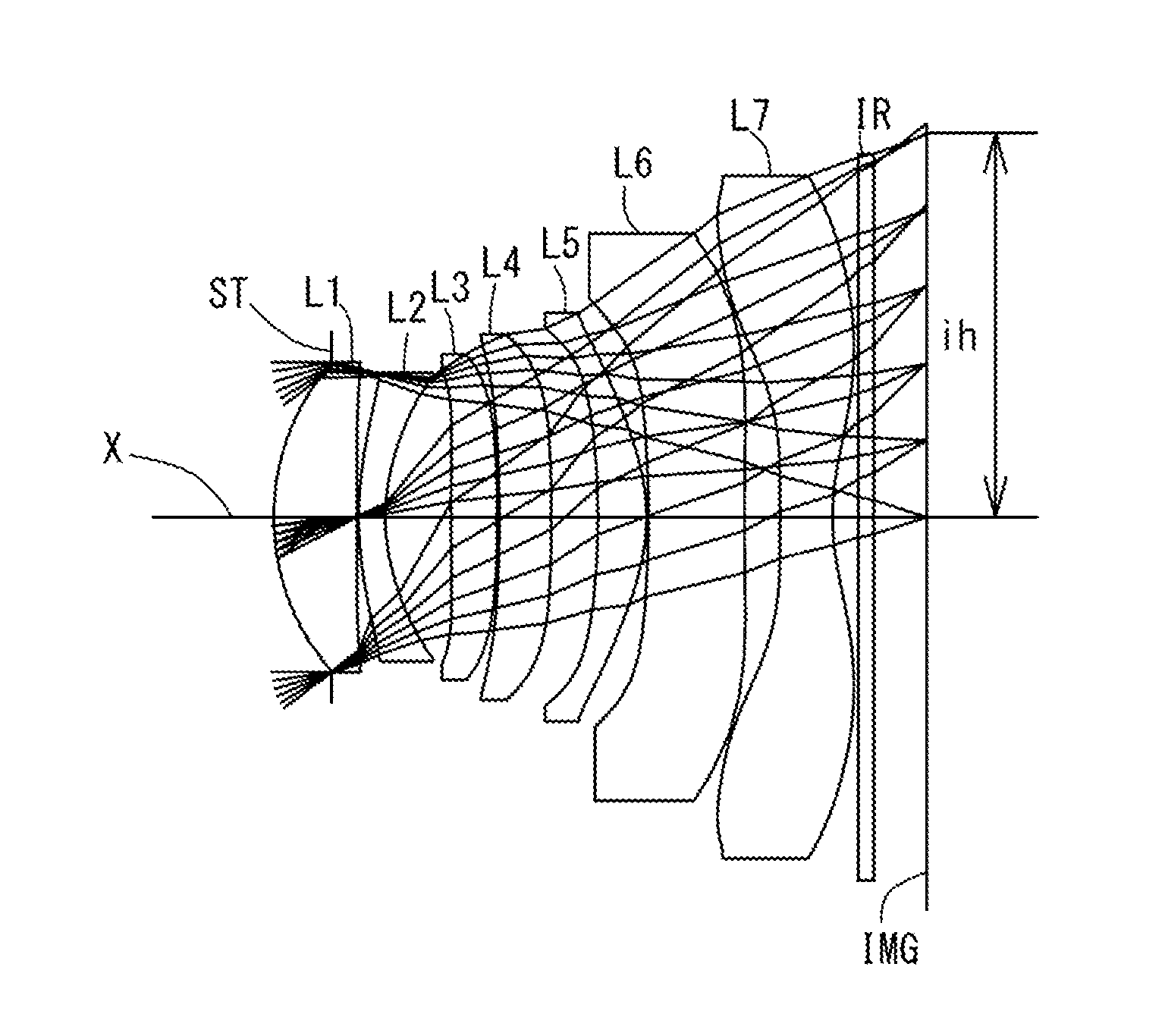
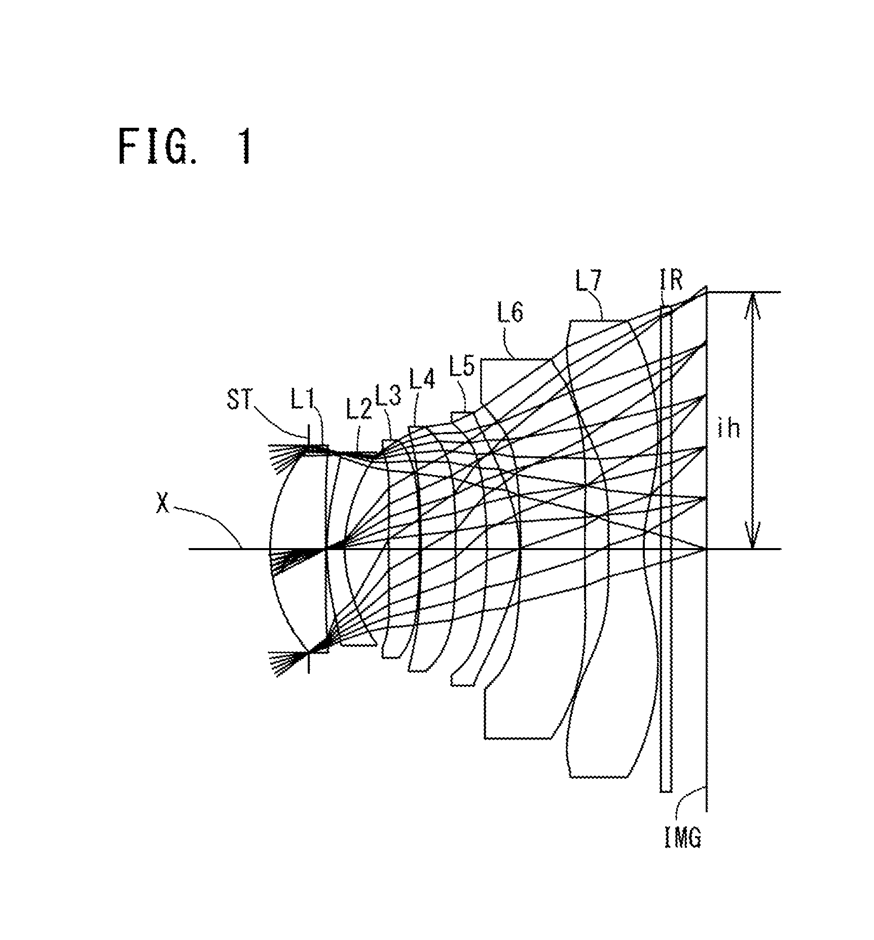
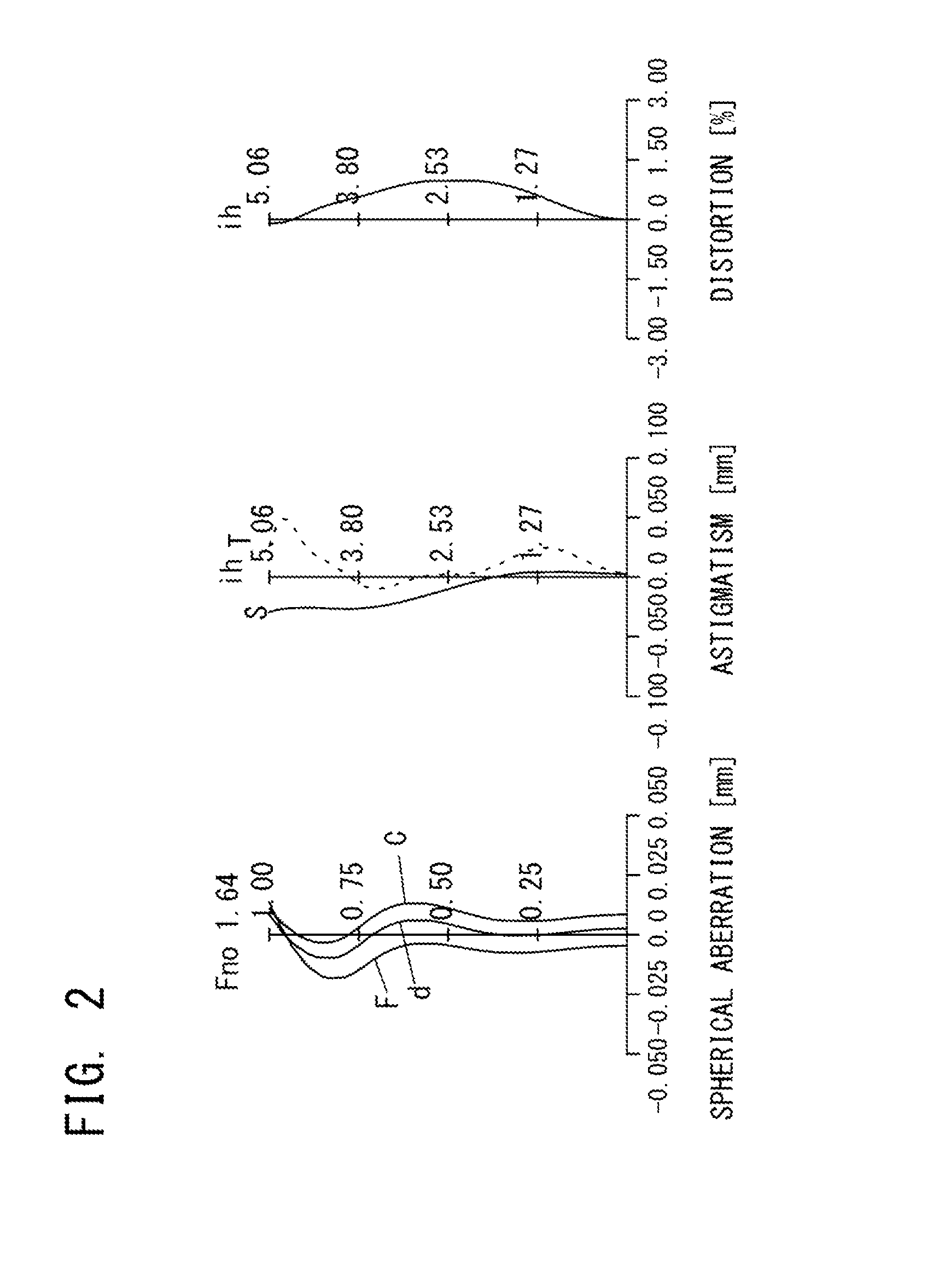
example 1
[0157]The Basic Lens Data of Example 1 is Shown Below in Table 1.
TABLE 1Example 1in mmf = 6.68Fno = 1.64ω(°) = 37.2ih = 5.06TTL = 8.52Surface DataSurfaceCurvatureSurfaceRefractiveAbbeNo. iRadius rDistance dIndex NdNumber νd(Object Surface)InfinityInfinity 1 (Stop)Infinity−0.760 2*3.1621.0921.543855.57 3*−77.6580.025 4*4.4060.3511.639123.25 5*2.5520.864 6*34.6550.6091.534855.66 7*−17.5670.025 8*−30.7310.6861.534855.66 9*−38.0000.61410*−11.0660.6421.534855.6611*−2.6010.02512*−14.1021.2671.614225.5813*99.0000.46914*−99.0000.6871.534855.6615*2.9230.33516Infinity0.2101.516864.2017Infinity0.695(Image Plane)InfinityConstituent Lens DataLensStart SurfaceFocal Length12 5.61 (=f1)24−10.25 (=f2)36 21.89 (=f3)48−310.57 (=f4) 510 6.20 (=f5)612−20.01 (=f6)714 −5.30 (=f7)LensComposite Focal Length3rd Lens-5th Lens 5.19 (=f345)6th Lens-7th Lens−3.94 (=f67)Aspheric Surface Data2nd Surface3rd Surface4th Surface5th Surface6th Surface7th Surface8th Surfacek0.000E+000.000E+000.000E+000.000E+000.000E+00...
example 2
[0160]The basic lens data of Example 2 is shown below in Table 2.
TABLE 2Example 2in mmf = 7.24Fno = 1.78ω(°) = 35.0ih = 5.06TTL = 8.98Surface DataSurfaceCurvatureSurfaceRefractiveAbbeNo. iRadius rDistance dIndex NdNumber νd(Object Surface)InfinityInfinity 1 (Stop)Infinity−0.737 2*3.1941.3061.543855.57 3*−99.0000.025 4*4.4340.3361.639123.25 5*2.5720.899 6*61.9670.5371.534855.66 7*−18.4620.025 8*99.0000.6431.534855.66 9*84.0000.70910*−12.7060.5901.534855.6611*−3.0320.02512*−11.4881.4971.614225.5813*−44.4930.41714*−99.0000.7801.534855.6615*3.1310.34016Infinity0.2101.516864.2017Infinity0.713(Image Plane)InfinityConstituent Lens DataLensStart SurfaceFocal Length12 5.72 (=f1)24−10.31 (=f2)36 26.66 (=f3)48−1052.35 (=f4) 510 7.29 (=f5)612−25.66 (=f6)714 −5.66 (=f7)LensComposite Focal Length3rd Lens-5th Lens 6.07 (=f345)6th Lens-7th Lens−4.33 (=f67)Aspheric Surface Data2nd Surface3rd Surface4th Surface5th Surface6th Surface7th Surface8th Surfacek0.000E+000.000E+000.000E+000.000E+000.000E+00...
example 3
[0163]The basic lens data of Example 3 is shown below in Table 3.
TABLE 3Example 3in mmf = 7.04Fno = 1.73ω(°) = 35.5ih = 5.06TTL = 8.69Surface DataSurfaceCurvatureSurfaceRefractiveAbbeNo. iRadius rDistance dIndex NdNumber νd(Object Surface)InfinityInfinity 1 (Stop)Infinity−0.771 2*3.0541.0311.543855.57 3*100.0000.030 4*3.5120.3001.634923.97 5*2.2240.893 6*−100.0000.5841.534855.66 7*−8.2850.093 8*−100.0000.6491.534855.66 9*100.0000.83210*−8.2310.6111.543855.5711*−2.9270.03312*−17.6711.2061.614225.5813*−100.0000.45414*100.0000.7281.534855.6615*2.9760.34016Infinity0.2101.516864.2017Infinity0.763(Image Plane)InfinityConstituent Lens DataLensStart SurfaceFocal Length12 5.77 (=f1)24−10.50 (=f2)36 16.85 (=f3)48−93.39 (=f4)510 8.03 (=f5)612−35.14 (=f6)714 −5.75 (=f7)LensComposite Focal Length3rd Lens-5th Lens 6.19 (=f345)6th Lens-7th Lens−4.73 (=f67)Aspheric Surface Data2nd Surface3rd Surface4th Surface5th Surface6th Surface7th Surface8th Surfacek0.000E+000.000E+000.000E+000.000E+000.000E+0...
PUM
 Abstract
Description
Claims
Application Information