Image Reading Device and Image Reading Method
a reading device and image technology, applied in the direction of character recognition, pile separation, transportation and packaging, etc., can solve the problem that the user cannot set the range (written page number position range) of image data, and achieve the effect of suppressing the complication of the structure of the image reading devi
- Summary
- Abstract
- Description
- Claims
- Application Information
AI Technical Summary
Benefits of technology
Problems solved by technology
Method used
Image
Examples
first embodiment
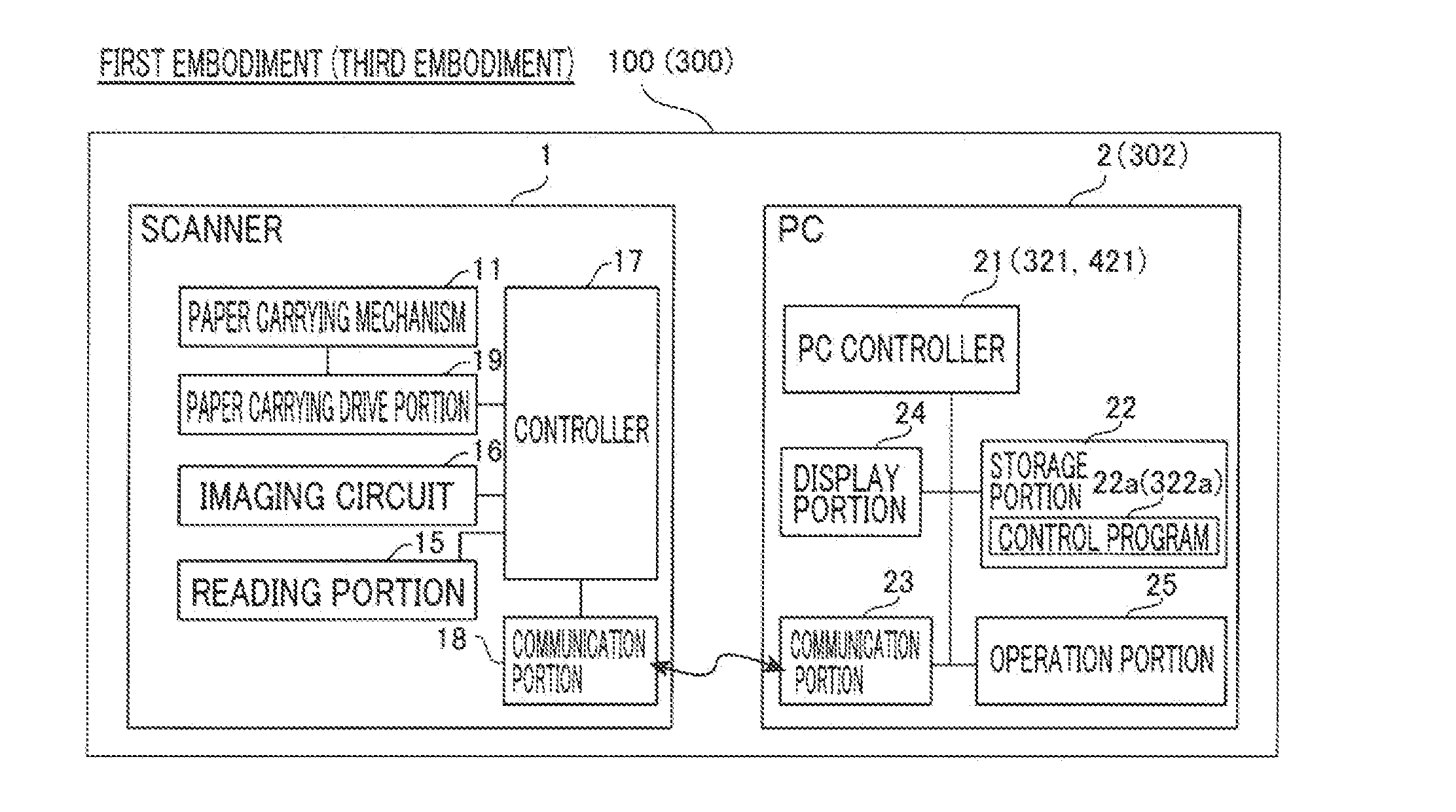
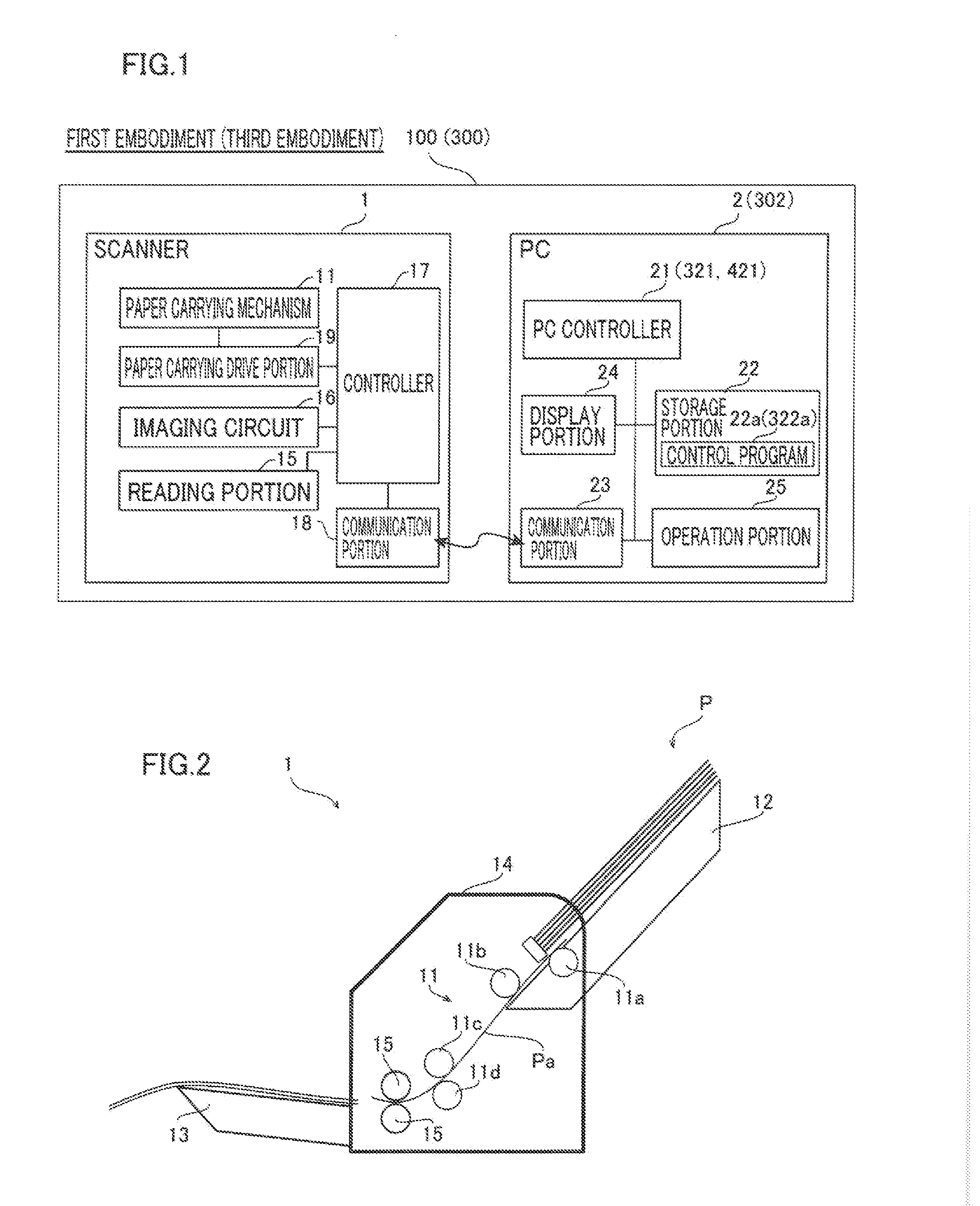
[0054]The overall structure of an image reading device 100 according to a first embodiment of the present invention is now described with reference to FIGS. 1 to 14. The image reading device 100 according to the first embodiment is configured as a so-called document scanner that reads a manuscript P with a plurality of (three or more, for example) pages as image data D for each page and stores the read image data D by a scanner 1 and a PC (personal computer) 2. The image reading device 100 may be configured as an image reading system including the scanner 1 and the PC 2. The manuscript P is an example of the “medium” in the claims.
[0055]As shown in FIG. 1, the image reading device 100 is provided with the scanner 1 and the PC 2. The scanner 1 and the PC 2 are configured to be capable of communication with each other and to be capable of transmitting the image data D, control signals, etc. to each other. The scanner 1 is configured to read the manuscript P with the plurality of pages...
example 1
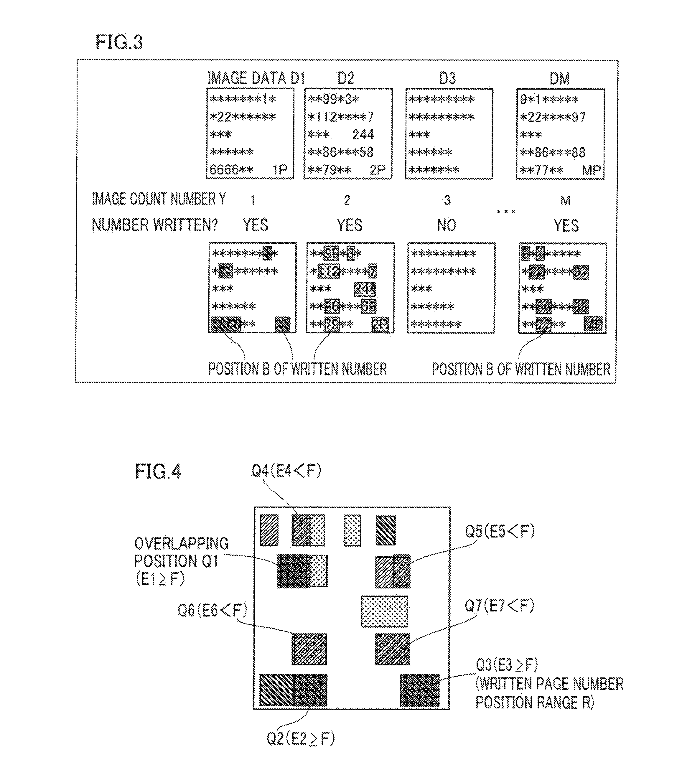
[0149]As shown in FIGS. 10 and 17, the page numbers X of the second image data D2 and the third image data D3 (whose image count numbers Y are 2 and 3) are not acquired in Example 1. In this case, it may be determined that there is the possibility of multi feed when the aforementioned processing for determining the possibility of multi feed (see FIG. 8) is performed.
[0150]First, it is determined whether or not the page number X5 of the fifth image data D5 is acquired at the step S30. In Example 1, the page number X5 of the fifth image data D5 (whose image count number Y is 5), which is 5, is acquired. Therefore, the processing for detecting the irregularity advances to the step S31.
[0151]At the step S31, it is determined whether or not the page number X1 of the first image data D1 is acquired. In Example 1, the page number X1 of the first image data D1 (whose image count number Y is 1), which is 1, is acquired. Therefore, the processing for detecting the irregularity advances to the...
example 2
[0154]As shown in FIGS. 10 and 17, the page numbers X are not acquired for every two pieces of image data from the first image data D1 in Example 2. In this case, it may be determined that there is the possibility of multi feed when the aforementioned processing for determining the possibility of multi feed (see FIG. 8) is performed.
[0155]First, it is determined whether or not the page number X10 of the tenth image data D10 is acquired at the step S30. In Example 2, the page number X10 of the tenth image data D10 (whose image count number Y is 10), which is 10, is acquired. Therefore, the processing for detecting the irregularity advances to the step S31.
[0156]At the step S31, it is determined whether or not the page number X1 of the first image data D1 is acquired. In Example 2, the page number X1 of the first image data D1 is not acquired. Therefore, the processing for detecting the irregularity advances to the step S35.
[0157]At the step S35, it is determined whether or not X10−X2...
PUM
 Abstract
Description
Claims
Application Information
 - R&D
- Intellectual Property
- Life Sciences
- Materials
- Tech Scout
- Unparalleled Data Quality
- Higher Quality Content
- 60% Fewer Hallucinations
Browse by: Latest US Patents, China's latest patents, Technical Efficacy Thesaurus, Application Domain, Technology Topic, Popular Technical Reports.
© 2025 PatSnap. All rights reserved.Legal|Privacy policy|Modern Slavery Act Transparency Statement|Sitemap|About US| Contact US: help@patsnap.com


