Passive polyphase filter
a polyphase filter and polyphase technology, applied in the field can solve the problems of complex configuration and complicated layout of passive polyphase filters, and achieve the effects of suppressing the complication of layout and wiring, reducing the influence of characteristics, and simple component layout and wiring shap
- Summary
- Abstract
- Description
- Claims
- Application Information
AI Technical Summary
Benefits of technology
Problems solved by technology
Method used
Image
Examples
first embodiment
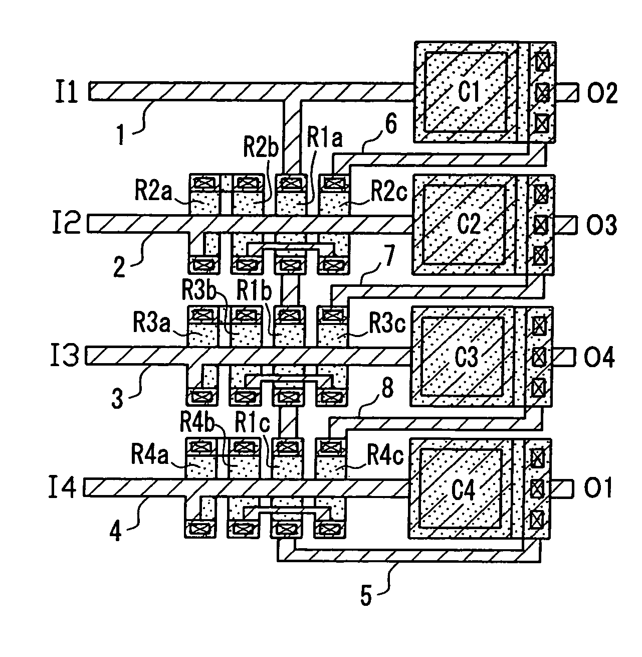
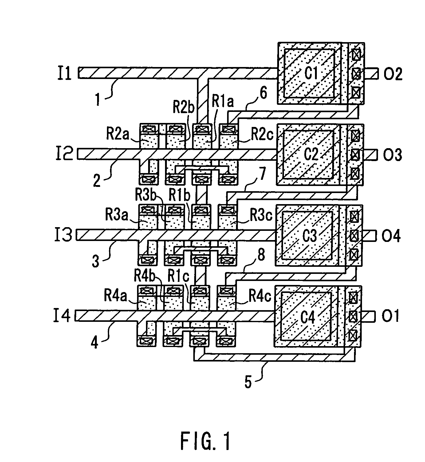
[0053]FIG. 1 is a plan view showing a layout of a passive polyphase filter according to a first embodiment. This layout configures a 4-phase input passive polyphase filter having the circuit structure of FIG. 20. In the explanation, components identical to those in the conventional examples as shown in FIGS. 21, 22 or the like will be assigned with the same reference numerals.
[0054]In the layout of FIG. 1, each of the resistors R1-R4 of FIG. 20 is divided into three parts and configured as a group of partial resistors. That is, the resistor R1 is composed of a group of partial resistors R1a-R1c, the resistor R2 is composed of a group of partial resistors R2a-R2c, the resistor R3 is composed of a group of partial resistors R3a-R3c, and the resistor R4 is composed of a group of partial resistors R4a-R4c. As clarified in the following embodiments, in the present invention, each of the resistors of m in number is divided into and configured as partial resistors of at least (m-1) in numb...
second embodiment
[0066]FIG. 6 is a circuit diagram of a 3-phase input passive polyphase filter in a second embodiment. Resistors R1-R3 and capacitors C1-C3 are connected in a loop, to which input nodes I1-I3 and output nodes O1-O3 are provided. FIG. 7 is a plan view showing a layout of the respective components of the 3-phase input passive polyphase filter shown in FIG. 6. The circuit structure and the layout of the respective components are the same substantially as those in the first embodiment, and thus the same reference numerals are assigned to the same components in order to avoid the duplicate explanation.
[0067]Each of the resistors R1-R3 in FIG. 6 is divided into two parts and composed as a group of partial resistors as in FIG. 7. The resistor R1 is composed of a group of partial resistors R1a-R1b, the resistor R2 is composed of a group of partial resistors R2a-R2b, and the resistor R3 is composed of a group of partial resistors R3a-R3b. For the resistors R2-R3, the partial resistors R2a-R2b...
third embodiment
[0072]FIG. 10 is a circuit diagram of a 5-phase input passive polyphase filter in a third embodiment. Resistors R1-R5 and capacitors C1-C5 are connected in a loop, to which input nodes I1-I5 and output nodes O1-O5 are provided. FIG. 11 is a plan view showing a layout of the respective components of the 5-phase input passive polyphase filter shown in FIG. 10. The circuit structure and a layout of the respective components are substantially the same as those in the first embodiment, and the same reference numerals are assigned to the same components in order to avoid the duplicate explanation.
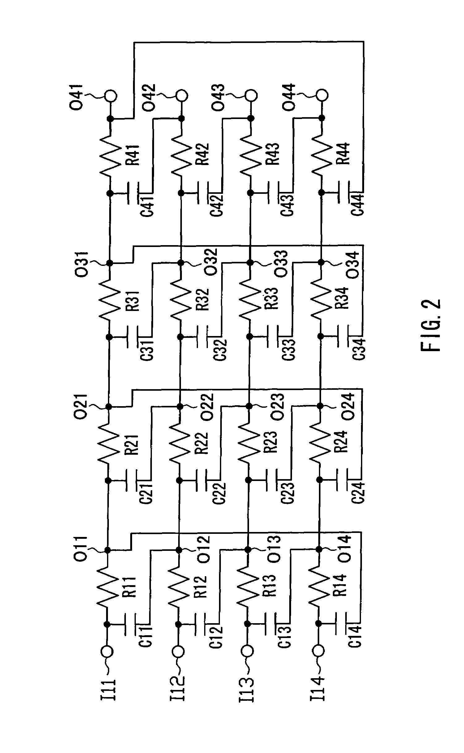
[0073]As an application example of the configuration in this embodiment, FIG. 12 shows a circuit diagram of a 3-stage 5-phase input passive polyphase filter. With respect to a first stage filter including resistors R11-R15 and capacitors C11-C15, a second stage filter including resistors R21-R25 and capacitors C21-C25 is connected at output nodes O11-O15 of the first stage filter. In the same man...
PUM
 Abstract
Description
Claims
Application Information
 - R&D
- Intellectual Property
- Life Sciences
- Materials
- Tech Scout
- Unparalleled Data Quality
- Higher Quality Content
- 60% Fewer Hallucinations
Browse by: Latest US Patents, China's latest patents, Technical Efficacy Thesaurus, Application Domain, Technology Topic, Popular Technical Reports.
© 2025 PatSnap. All rights reserved.Legal|Privacy policy|Modern Slavery Act Transparency Statement|Sitemap|About US| Contact US: help@patsnap.com


