Check patentability & draft patents in minutes with Patsnap Eureka AI!

Movable foil blade for papermaking on a fourdrinier, including the lead blade on the forming board box

a papermaking and foil blade technology, applied in the field of continuous paper sheet forming machines having a fourdrinier table, can solve the problems of increasing the load on the actuator at the expense of the course, and achieve the effects of reducing load, good formation, retention and control of sheet properties

Active Publication Date: 2016-05-12
HOUSE RICHARD L +1
View PDF2 Cites 1 Cited by
  • Summary
  • Abstract
  • Description
  • Claims
  • Application Information

AI Technical Summary

Benefits of technology

The invention aims to improve the quality of sheets produced in the papermaking process. It achieves this by moving the leading edge of the forming board to the proper location to split the impingement of the jet from the slice opening of the headbox and improve sheet formation, retention, and control of sheet properties. Additionally, it maintains the spacing between foils downstream of the follower blade, without impacting any changes in the harmonics of the papermaking process. Furthermore, the invention provides a slide base with rolling surfaces to reduce loading on the jack screw actuator for moving the lead blade back and forth along the plurality of guide bars.

Problems solved by technology

This is of course at the expense of increased loading on the actuator that moves the blade.
Additionally, the actuator providing the force in prior art is not pulling in the same direction as the oblique angle of the slide requiring additional linkage and pin connections to move the blade at additional cost to manufacture the equipment.

Method used


Image

  • Movable foil blade for papermaking on a fourdrinier, including the lead blade on the forming board box
  • Movable foil blade for papermaking on a fourdrinier, including the lead blade on the forming board box
  • Movable foil blade for papermaking on a fourdrinier, including the lead blade on the forming board box

Examples


first embodiment

—FIGS. 1, 2, 3, 3a, 4, 5, 5a, 6, &6a

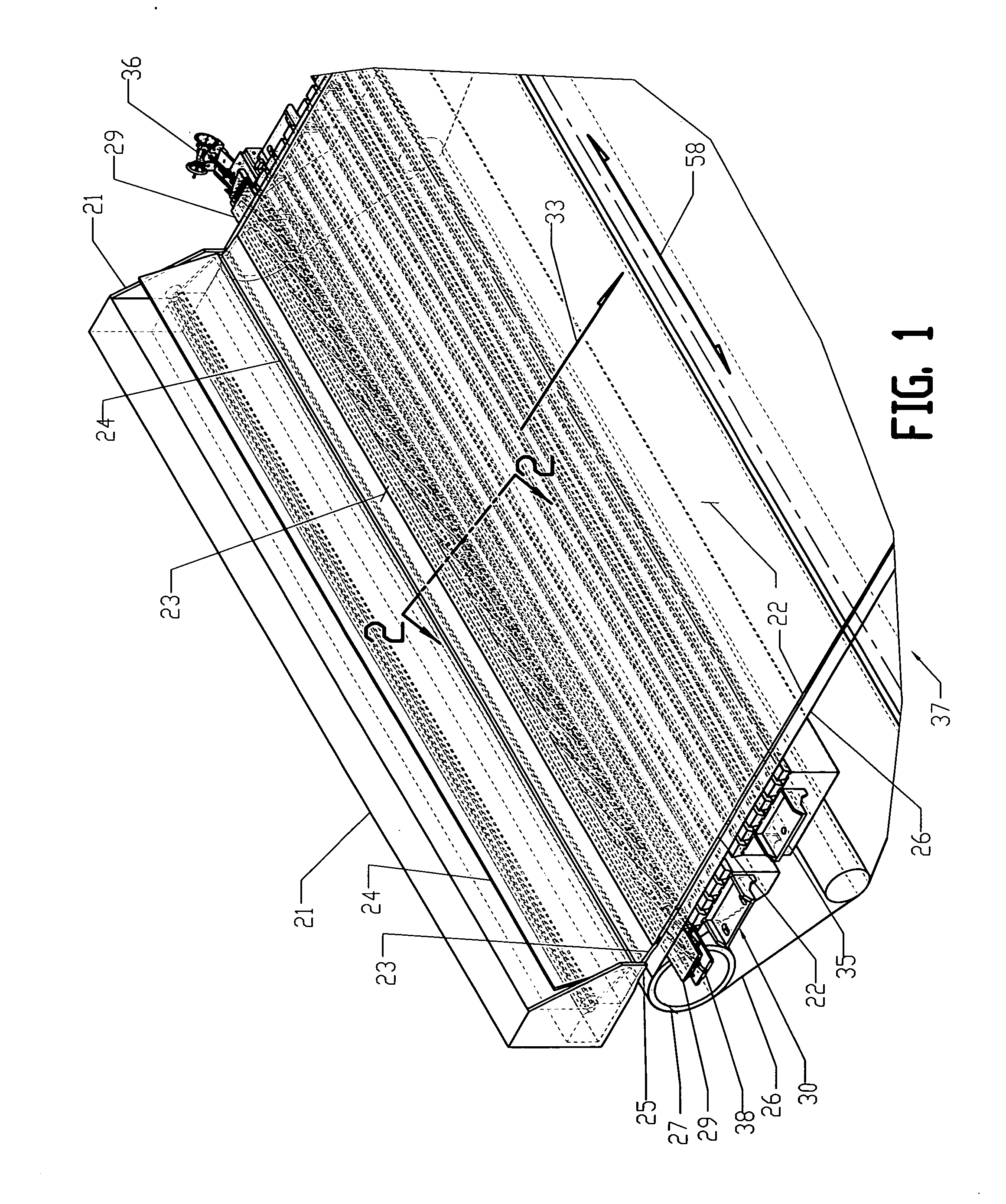
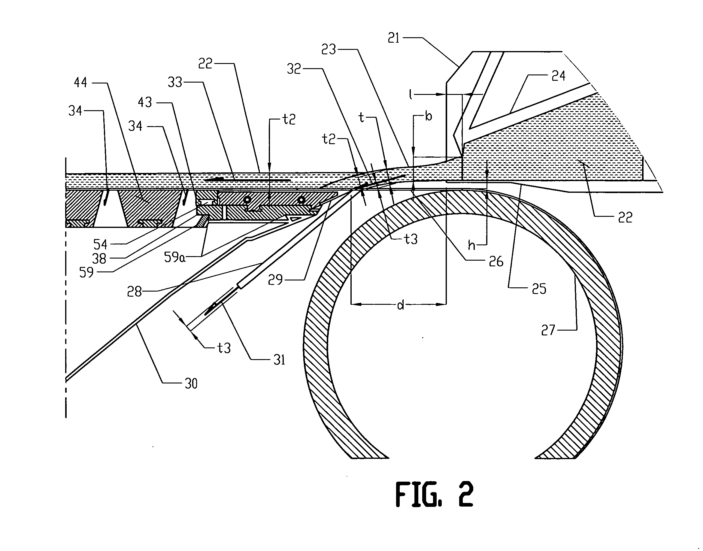
[0119]FIG. 1 illustrates a typical Fourdrinier at the wet end including the headbox 21 and the first two drainage boxes, the forming board 30 and the next gravity drainage box 35. Just below the Headbox 21 is the breast roll 27 and a wire return roll 27a for which the wire 26 extends over and around the breast roll 27 and continues down the Fourdrinier 37 in the direction 33. The wire 26 is supported by drainage elements, two of which are shown in FIG. 1, the forming board 30 and the first gravity box 35. Under ideal conditions the slurry 22 inside the headbox 21 forms a jet 23 which emerges out of the slice opening of the headbox 21 and impinges directly on the wire 26 and in the proper position for which the leading edge of the lead blade 29 of the forming board 30 will split the flow of the slurry 22 into two flows. The majority of this flow of slurry 22 will stay in a horizontal direction 33 to be drained of water down the length of the Fourd...

third embodiment

DETAILED DESCRIPTION—FIGS. 10, 10a, 11, &11a

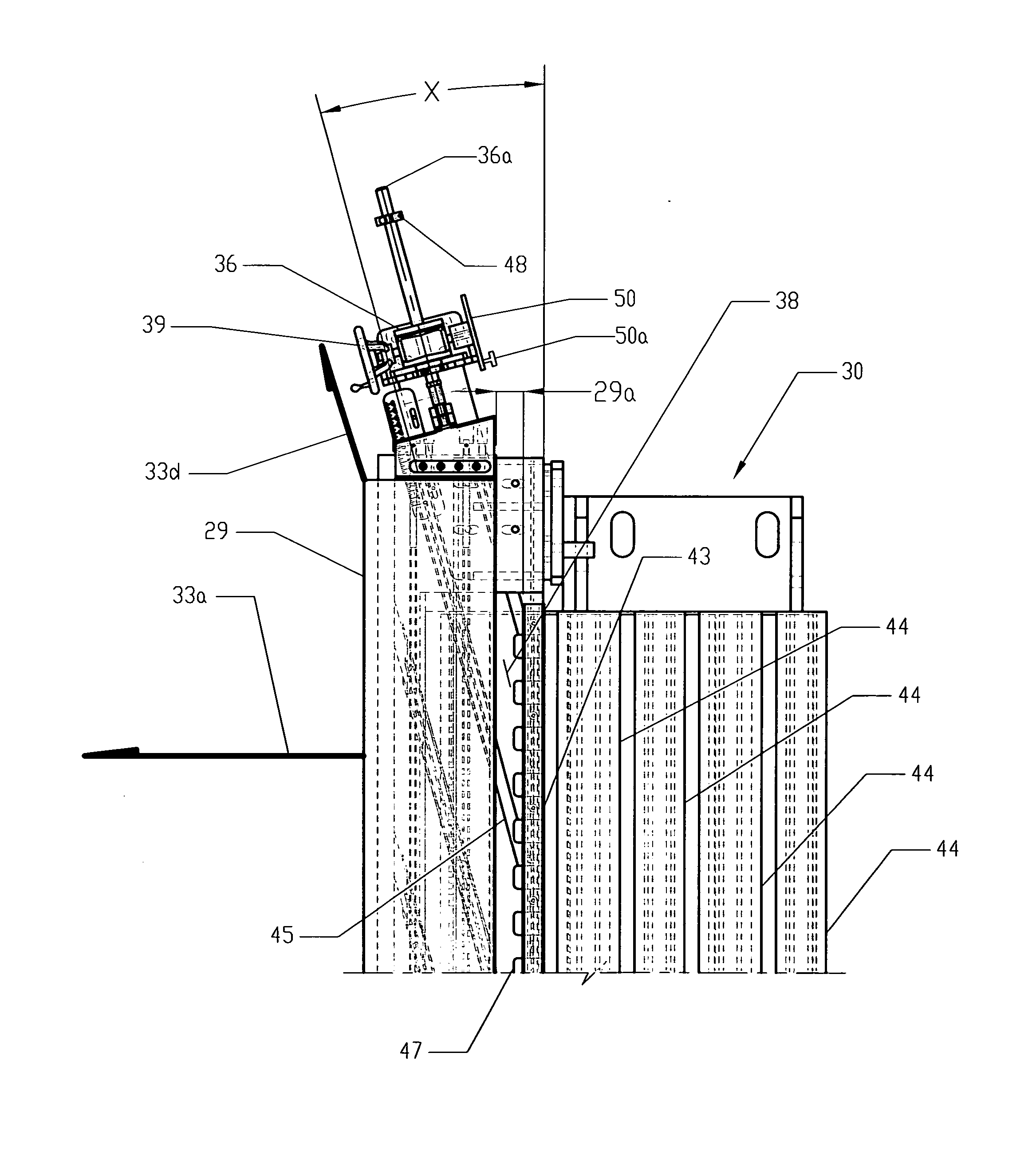
[0159]FIGS. 10, 10a, 11, &11a is an alternative embodiment for moving the lead blade 29 such that the jack screw actuator 36 is no longer needed on the back side of the Fourdrinier to move the lead blade 29. This is illustrated in FIG. 10. The jack screw actuator 36 is replaced with a plurality of servo gear-motor drives 68 shown in the hidden lines in FIG. 10.

[0160]FIG. 10a is a sectional view that shows one of the servo gear-motor drives 68 that is keyed to the gear tooth pinion 65c and can rotate pinion gear 65c such that the guide bar 46a with matching gear teeth will move the lead blade 29 in unison with the other servo gear-motor drives 68 to the desired position as shown in FIG. 2. These servo gear-motor drives 68 can be a right angle gearbox arrangement to keep the profile of the gear-motor as small as possible and to allow for a cover 68a to protect the servo gear-motor 68 from fluid flow of the slurry 22 drainage through the wir...


PUM


Abstract

A method for operably adjusting a forming board lead blade of a paper sheet forming machine of the type having a headbox for impinging a jet of slurry from a slice opening of the headbox onto the surface of a porous wire moving continuously in a horizontal machine direction over the forming board.

Description

CROSS-REFERENCE TO RELATED APPLICATIONS[0001]US patent numbers; Ibrahim U.S. Pat. No. 4,684,441, issued Aug. 4, 1987, Ibrahim U.S. Pat. No. 4,718,983, issued Jan. 12, 1988, Miller U.S. Pat. No. 5,421,961, issued Jun. 6, 1995, Mellen U.S. Pat. No. 4,278,497, issued Jul. 14, 1981, and Mellen U.S. Pat. No. 4,280,869, issued Jul. 28, 1981.TECHNICAL FIELD[0002]This invention relates to continuous paper sheet forming machines having a Fourdrinier table and more particularly relates to improvements in the forming board of such machines which result in good formation, retention and control of sheet properties.BACKGROUNDPrior Art[0003]FIG. 1 shows a typical papermaking machine with a Fourdrinier table 37 and the first part of the sheet forming process. This process is typically characterized by the provision of a headbox 21 for directing a jet 23 of papermaking slurry 22, exiting out of the slice opening of the headbox 21 and impinging on the upper surface of the Fourdrinier table 37 just do...

Claims


Application Information

Patent Timeline
IPC IPC(8): D21F1/48
CPCD21F1/486
Inventor HOUSE, RICHARD L.HILLS, JR., WARREN
Owner HOUSE RICHARD L
Features
  • R&D
  • Intellectual Property
  • Life Sciences
  • Materials
  • Tech Scout
  • Unparalleled Data Quality
  • Higher Quality Content
  • 60% Fewer Hallucinations
Learn More