Thermal management system for a gas turbine engine

a technology of thermal management system and gas turbine engine, which is applied in the direction of machines/engines, efficient propulsion technologies, transportation and packaging, etc., can solve the problem of reducing the efficiency of the engin

Active Publication Date: 2016-05-12
RTX CORP
View PDF13 Cites 69 Cited by
  • Summary
  • Abstract
  • Description
  • Claims
  • Application Information

AI Technical Summary

Problems solved by technology

Existing thermal management systems typically dispose at least a portion of the heat exchangers in the fan duct in a manner that creates drag on the air passing through the fan duct.
The creation of drag on the air passing through the fan duct decreases the efficiency of the engine.

Method used


Image

  • Thermal management system for a gas turbine engine
  • Thermal management system for a gas turbine engine
  • Thermal management system for a gas turbine engine

Examples


Embodiment Construction

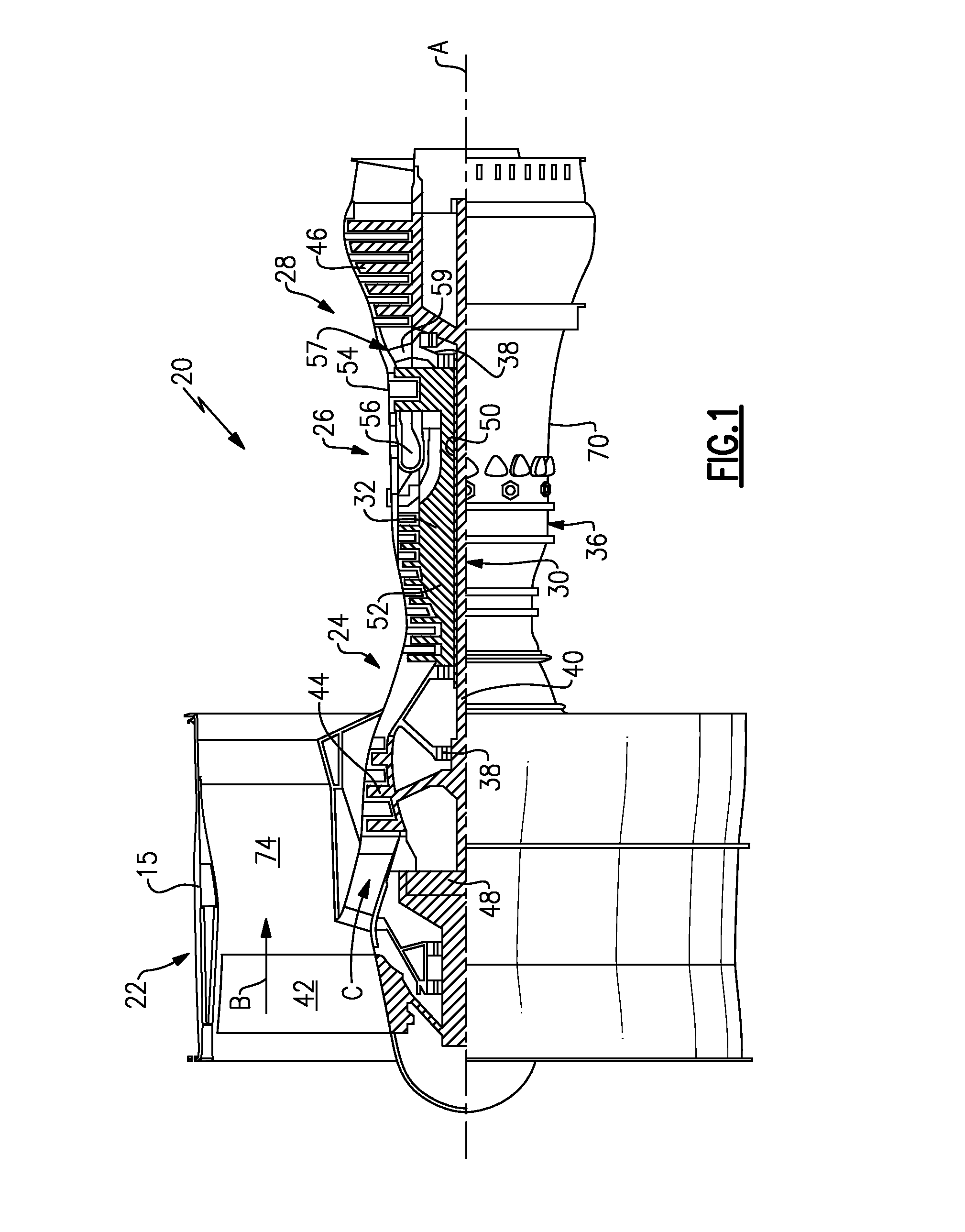
[0028]FIG. 1 schematically illustrates a gas turbine engine 20. The gas turbine engine 20 is disclosed herein as a two-spool turbofan that generally incorporates a fan section 22, a compressor section 24, a combustor section 26 and a turbine section 28. Alternative engines might include an augmentor section (not shown) among other systems or features. The fan section 22 drives air along a bypass flow path B in a bypass duct 74 defined at least partially within a fan case 15, while the compressor section 24 drives air along a core flow path C for compression and communication into the combustor section 26 then expansion through the turbine section 28. Although depicted as a two-spool turbofan gas turbine engine in the disclosed non-limiting embodiment, it should be understood that the concepts described herein are not limited to use with two-spool turbofans as the teachings may be applied to other types of turbine engines including three-spool architectures.

[0029]The exemplary engine...


PUM


Abstract

In one exemplary embodiment, a gas turbine engine system for cooling engine components includes an engine core, a core housing containing the engine core, an engine core driven fan forward of the core housing, a nacelle surrounding the fan and the core housing, and a bypass duct defined between an outer diameter of the core housing and an inner diameter of the nacelle. Also included is a thermal management system having a coolant circuit including at least one of a first heat exchanger disposed on the inner diameter of the nacelle and a second heat exchanger disposed on a leading edge of a BiFi spanning the bypass duct. The first heat exchanger is in thermal communication with the second heat exchanger.

Description

CROSS-REFERENCE TO RELATED APPLICATION[0001]This application claims priority to U.S. Provisional Application No. 62 / 076,161 filed Nov. 6, 2014.TECHNICAL FIELD[0002]The present disclosure relates generally to liquid cooled thermal management systems for a gas turbine engine, and more specifically to an integrated fan liquid cooled thermal management system.BACKGROUND[0003]Gas turbine engines, such as those utilized on commercial aircraft, include a compressor operable to compress air, a combustor that mixes the compressed air with a fuel and ignites the mixture, and a turbine section that is driven to rotate by expansion of the resultant combustion gasses. The compressor, combustor and turbine are contained within an engine core. In some engines a fan is mounted at the front of the engine core. The rotation of the fan is driven by the turbine. In some gas turbine engines, referred to as turbofan engines, the fan drives air into the compressor and into a fan duct surrounding the engin...

Claims


Application Information

Patent Timeline
Patent Type & Authority Applications(United States)
IPC IPC(8): F02C7/16F02C7/047
CPCF02C7/16F05D2260/213F05D2220/32F02C7/047F01D25/162F02K3/06F05D2260/98F02C7/14Y02T50/60B64D15/06F02C7/12B64D15/02B64D15/00F01D25/02
Inventor BINTZ, MATTHEW E.GENDRICH, CHARLES P.DITOMASSO, JOHN C.MURPHY, ANDREW J.
Owner RTX CORP
Why Eureka
Try Eureka