Appliance for dehumidification and multi-function appliance for dehumidificaton or humidification

a multi-functional appliance and dehumidification technology, applied in the direction of heating types, domestic cooling devices, separation processes, etc., can solve problems such as difficulties and difficulties, and achieve the effects of reducing the size of the appliance for dehumidification or humidification, facilitating separation or mounting, and improving user convenience and reliability

Active Publication Date: 2016-05-12
SAMSUNG ELECTRONICS CO LTD
View PDF1 Cites 39 Cited by
  • Summary
  • Abstract
  • Description
  • Claims
  • Application Information

AI Technical Summary

Benefits of technology

[0056]In accordance with an aspect of the present disclosure, as a water container configured to store condensation water generated from a cooling apparatus is detachably provided at an upper portion of an appliance for humidification, a user may easily separate or mount the water container from a body of the appliance for humidification when the water container needs to be emptied, i.e., when the water container is full, or when the emptied water container needs to be re-mounted.
[0057]In accordance with an aspect of the present disclosure, an appliance for dehumidification or humidification is provided with a combined water container provided with a condensation water container and a humidification water container integrally combined, and thus the size of the appliance for dehumidification or humidification may be reduced.
[0058]In accordance with an aspect of the present disclosure, a water container is formed in the shape of a ring having a hollow hole, and as a guide unit inserted into the ho

Problems solved by technology

The water container is detachably provided at a lower portion of the appliance for dehumidification, and when the water container is full and needs to be emptied, difficulties may be present as a user may need to be

Method used


Image

  • Appliance for dehumidification and multi-function appliance for dehumidificaton or humidification
  • Appliance for dehumidification and multi-function appliance for dehumidificaton or humidification
  • Appliance for dehumidification and multi-function appliance for dehumidificaton or humidification

Examples


first embodiment

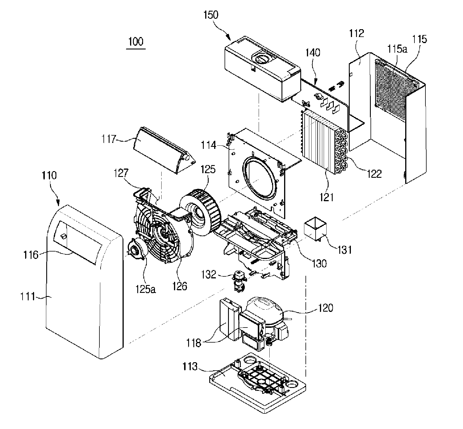
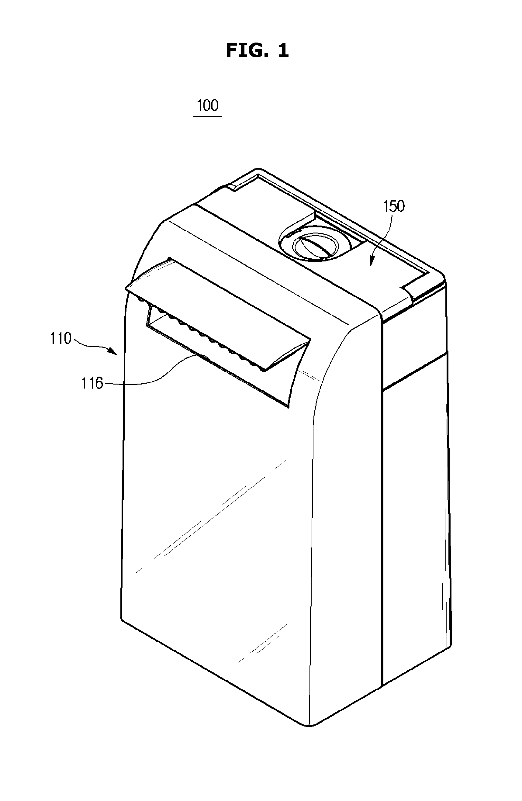
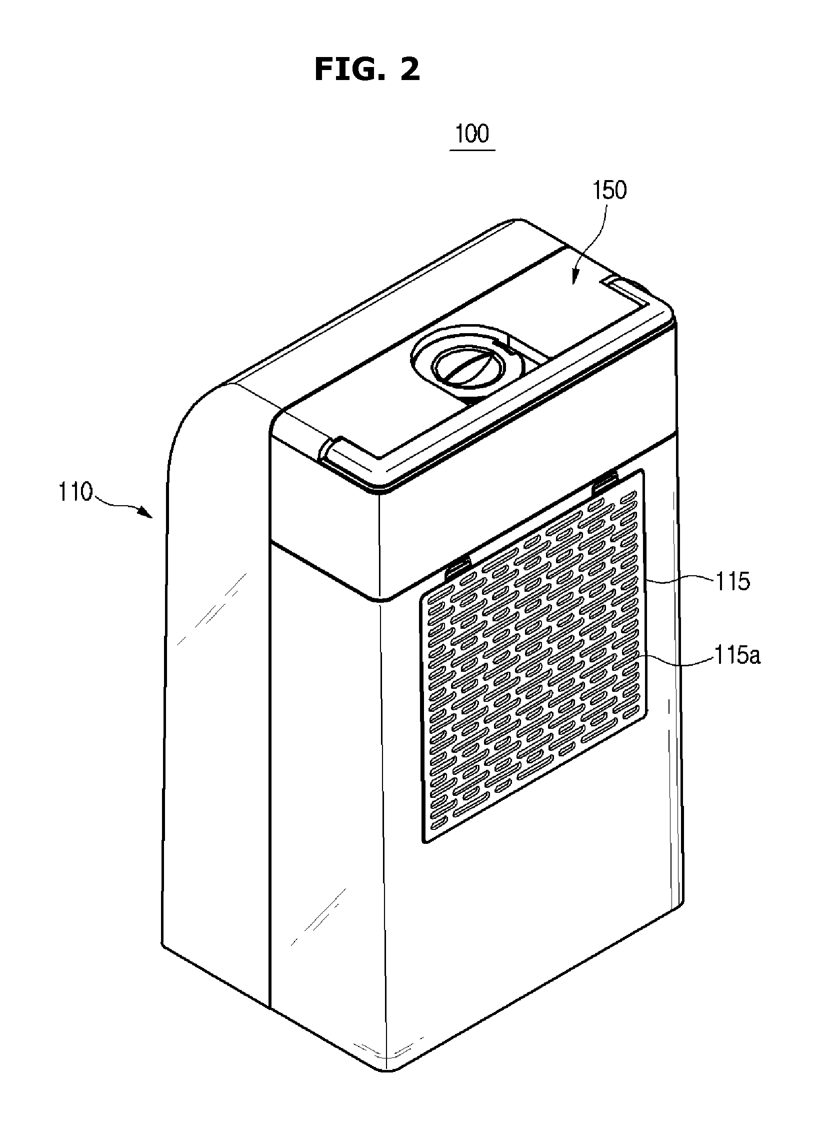
[0108]FIG. 1 is a perspective view illustrating an external appearance of an appliance for dehumidification according to the present disclosure, FIG. 2 is a perspective view from a different angle illustrating the external appearance of the appliance for dehumidification of FIG. 1, FIG. 3 illustrates a water container separated from the appliance for dehumidification of FIG. 1, FIG. 4 is an exploded perspective view illustrating disassembled main structures of the appliance for dehumidification of FIG. 1, FIG. 5 is a side cross-sectional view of the appliance for dehumidification of FIG. 1, and FIG. 6 is a frontal view of the appliance for dehumidification of FIG. 1.

[0109]Referring to FIG. 1 to FIG. 6, an appliance for dehumidification 100 includes a body 110 having an inflow unit 115 and an outflow unit 116, a draft fan 125 to forcedly move air, a cooling cycle apparatus having a compressor 120 to compress refrigerant, a condenser 121, or a heat-exchanging apparatus, to condense th...

second embodiment

[0139]FIG. 11 is a perspective view of an external appearance of an appliance for dehumidification according to the present disclosure, FIG. 12 is a perspective view from a different angle illustrating the external appearance of the appliance for dehumidification of FIG. 11, FIG. 13 illustrates a water container separated from the appliance for dehumidification of FIG. 11, FIG. 14 illustrates a disassembled drain pipe of the appliance for dehumidification of FIG. 11, FIG. 15 is a side cross-sectional view of the appliance for dehumidification of FIG. 11, and FIG. 16 is a side cross-sectional view illustrating a consecutive drain pipe of the appliance for dehumidification of FIG. 11.

[0140]Referring to FIG. 11 to FIG. 16, the appliance for dehumidification according to the second embodiment of the present disclosure will be described.

[0141]An appliance for dehumidification 200 includes a body 210 having an inflow unit 215 and an outflow unit 216, a cooling cycle apparatus having a com...

third embodiment

[0154]FIG. 17 is a perspective view of an external appearance of an appliance for dehumidification according to the present disclosure, FIG. 18 is a perspective view from a different angle illustrating the external appearance of the appliance for dehumidification of FIG. 17, FIG. 19 illustrates a water container separated from the appliance for dehumidification of FIG. 17, and FIG. 20 is a side cross-sectional view of the appliance for dehumidification of FIG. 17.

[0155]Referring to FIG. 17 to FIG. 20, the appliance for dehumidification according to the third embodiment of the present disclosure will be described. With respect to the structures that are identical to the previously described structures, the same numeric expressions may be applied, and the descriptions of the structures as such may be omitted.

[0156]An appliance for dehumidification 300 includes a body 310 having an inflow unit 315 and an outflow unit 316, a cooling cycle apparatus having a compressor 320 to compress re...


PUM


Abstract

An appliance for dehumidification, with a body having an inflow unit and an outflow unit; a heat-exchanging apparatus to condense vapor in the air; a fan to forcedly move the air; a tray to collect condensation water descending from a cooling apparatus; a water container detachably provided at an upper portion of the body to store the condensation water; a pump to pump the condensation water from the tray to the water container; and a drain pipe to guide the condensation water from the pump to the water container. The water container may be easily separated from the appliance to empty the water container when the water container is full, and then the water container may be easily mounted again.

Description

CROSS-REFERENCE TO RELATED APPLICATIONS[0001]This application claims the benefits of the Korean Patent Application No. 10-2014-0157310, filed on Nov. 12, 2014 and the Korean Patent Application No. 10-2015-0098908 filed on Jul. 13, 2015, in the Korean Intellectual Property Office, the disclosures of which are incorporated herein by reference.BACKGROUND[0002]1. Field[0003]Embodiments of the present disclosure relate to an appliance for dehumidification and an appliance for dehumidification or humidification configured to control humidity.[0004]2. Description of the Related Art[0005]In general, an appliance for dehumidification is an apparatus configured to remove moisture in air. The appliance for dehumidification may largely be divided into a drying-type appliance for dehumidification and a cooling-type appliance for dehumidification. The drying-type appliance for dehumidification is provided with a method to perform a dehumidification by absorbing or adsorbing moisture in air by use...

Claims


Application Information

Patent Timeline
IPC IPC(8): F24F3/14B01D53/04B01D53/26
CPCF24F3/14B01D53/0438B01D53/265B01D53/261F24F13/222F24F2006/008B01D2257/80F24F3/1411F24F2003/1446F24F3/1405
Inventor CHOI, HEUNG SEOBMYEONG, SEONG RYEOLKWON, JUN HYOUNKIM, SUNG WOOKIMCHU, EUY SUNG
Owner SAMSUNG ELECTRONICS CO LTD
Why Eureka
Try Eureka