

Autonomous mobile body
a mobile body and autonomous technology, applied in the direction of carpet cleaners, distance measurement, instruments, etc., can solve the problem of not being able to properly correct a self-position, and achieve the effect of improving the accuracy of position estimation and reducing the probability of treating
- Summary
- Abstract
- Description
- Claims
- Application Information
AI Technical Summary
Benefits of technology
Problems solved by technology
Method used
Image

Examples
embodiment 1
[0033]The following description discusses an embodiment of the present invention with reference to FIGS. 1 through 14. Embodiment 1 shows a cleaning robot as an example of an autonomous mobile body. Note, however, that the present invention is not limited to the cleaning robot.
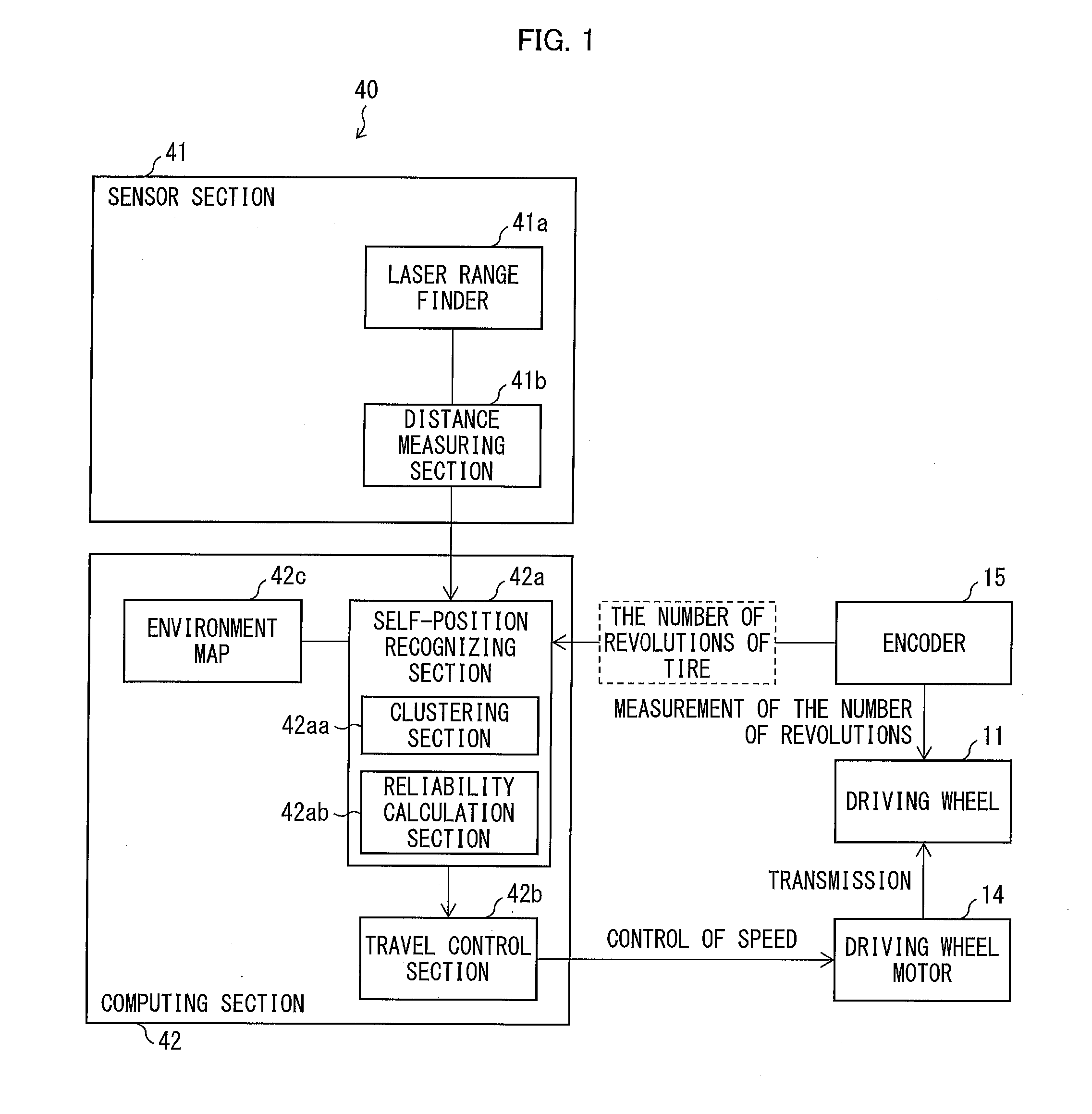
[0034]First, the following description discusses, with reference to (a) and (b) of FIG. 2, a configuration of the cleaning robot of Embodiment 1 which cleaning robot serves as an autonomous mobile body. (a) of FIG. 2 is a perspective view illustrating the configuration of the cleaning robot. (b) of FIG. 2 is a cross sectional view, taken along a cutting line A-A′ shown in (a) of FIG. 2.
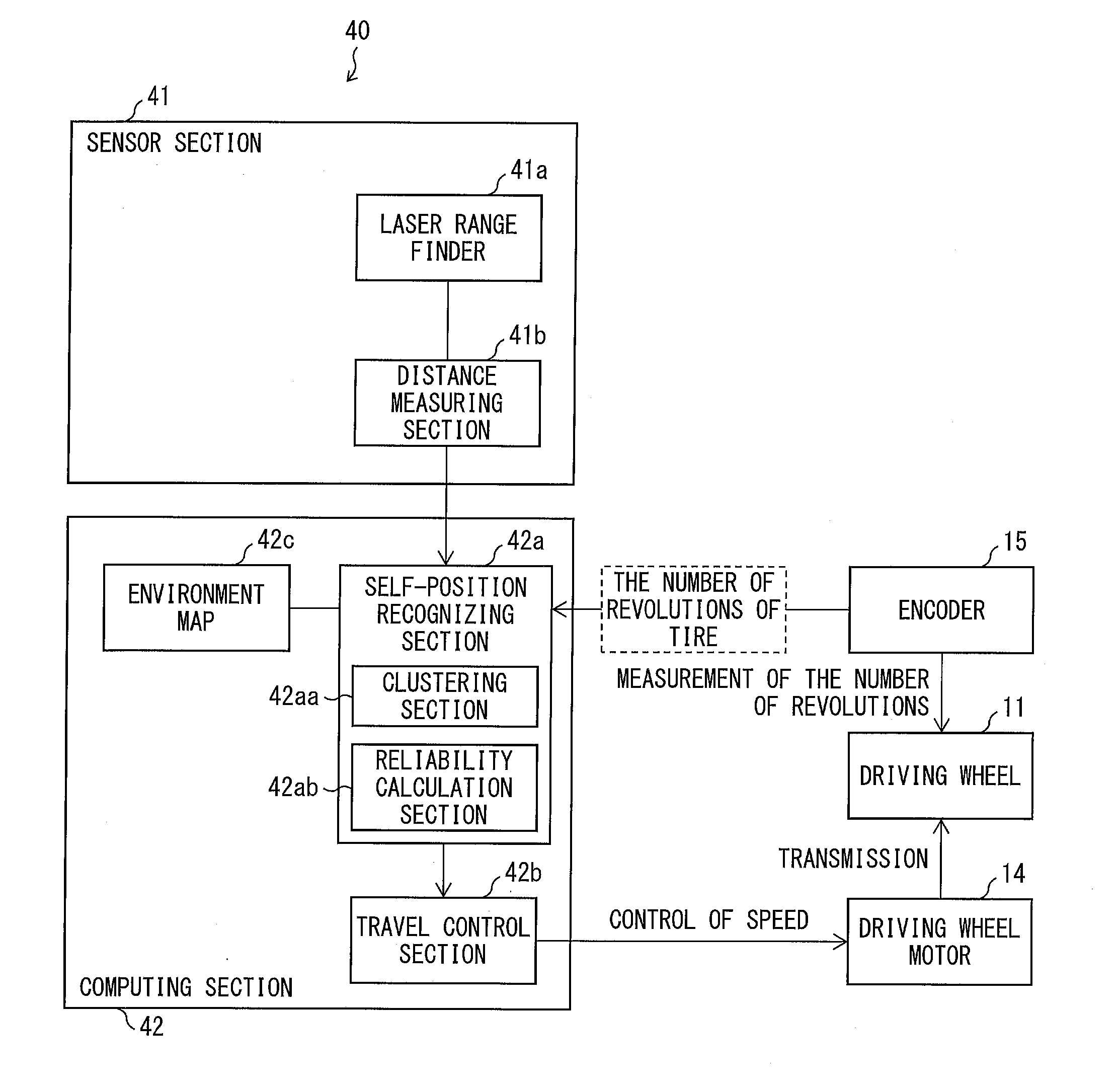
[0035]A cleaning robot 1 of Embodiment 1 includes a driving mechanism 10, a cleaning mechanism 20, a housing 30, and a sensor mechanism 40 as illustrated in (a) and (b) of FIG. 2.
[0036]The driving mechanism 10 includes (i) two driving wheels 11 which are provided on right and left sides of a back bottom part of the cleaning robo...
embodiment 2
[0139]The following description discusses another embodiment of the present invention with reference to FIG. 15. Note that configurations other than those described in Embodiment 2 are identical to the configurations described in Embodiment 1. For convenience, members having functions identical to those illustrated in the drawing of Embodiment 1 are given identical reference signs, and descriptions on such members are omitted.
[0140]The cleaning robot 1 of Embodiment 1, which cleaning robot 1 serves as an autonomous mobile body, uses a grid map as an environment map 42c. Meanwhile, a cleaning robot 1 of Embodiment 2, which cleaning robot 1 serves as an autonomous mobile body, differs from the cleaning robot 1 of Embodiment 1 in that the cleaning robot 1 of Embodiment 2 employs a form in which an obstacle object is directly drawn in an environment map.
[0141]The following description discusses, with reference to FIG. 15, a case where the cleaning robot of Embodiment 2 is realized by us...
embodiment 3
[0146]The following description discusses another embodiment of the present invention with reference to FIG. 16. Note that configurations other than those described in Embodiment 3 are identical to the configurations described in Embodiments 1 and 2. For convenience, members having functions identical to those illustrated in the drawings of Embodiment 1 and 2 are given identical reference signs, and descriptions on such members are omitted.
[0147]The cleaning robot 1 of Embodiment 1, which cleaning robot 1 serves as an autonomous mobile body, is configured such that in a case where a distance between adjacent obstacle measurement points is less than a threshold with respect to a measurement direction of the laser range finder 41a, such obstacle measurement points are treated as one cluster. Meanwhile, a cleaning robot 1 of Embodiment 3, which cleaning robot 1 serves as an autonomous mobile body, differs from the cleaning robot 1 of Embodiment 1 in terms of standards for determining w...
PUM
 Abstract
Description
Claims
Application Information