
Switched reluctance motor sensorless method based on difference inductance vector method

A switched reluctance motor and sensor technology, used in motor generator control, electronic commutation motor control, and generator control, etc., can solve the problems of switched reluctance motor nonlinearity, low position estimation accuracy, and inductance saturation.

Inactive Publication Date: 2021-05-11
DALIAN MARITIME UNIVERSITY
View PDF2 Cites 0 Cited by
  • Summary
  • Abstract
  • Description
  • Claims
  • Application Information

AI Technical Summary

Problems solved by technology

The traditional position sensorless control of switched reluctance motor based on the inductance method uses inductance information to estimate the rotor position angle. Linear, so that the inductor will saturate
At this time, when the saturated inductance is used to estimate the rotor position information, the position estimation accuracy is not high

Method used


Image

  • Switched reluctance motor sensorless method based on difference inductance vector method
  • Switched reluctance motor sensorless method based on difference inductance vector method
  • Switched reluctance motor sensorless method based on difference inductance vector method

Examples


Embodiment Construction

[0040] In order to make the technical solutions and advantages of the present invention more clear, the technical solutions in the embodiments of the present invention are clearly and completely described below in conjunction with the drawings in the embodiments of the present invention:

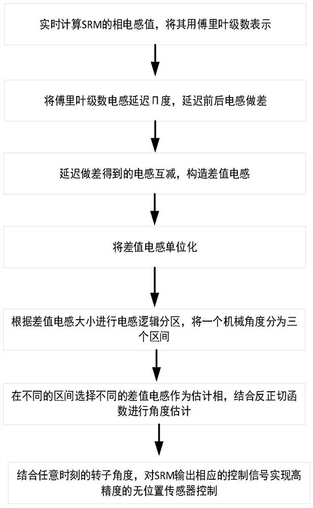
[0041] figure 1 It is a flow chart of the position sensorless control method of the switched reluctance motor of the present invention; this embodiment provides the steps of the above-mentioned position sensorless control method of the switched reluctance motor based on the differential inductance vector method, specifically:

[0042] S1: Calculate the three-phase inductance value of the switched reluctance motor in real time, and express the three-phase inductance value in the form of Fourier series to obtain the three-phase inductance value expressed in the form of Fourier series;

[0043] S2: Delay the three-phase inductance value expressed in the form of Fourier series by π degree to obt...


PUM


Abstract

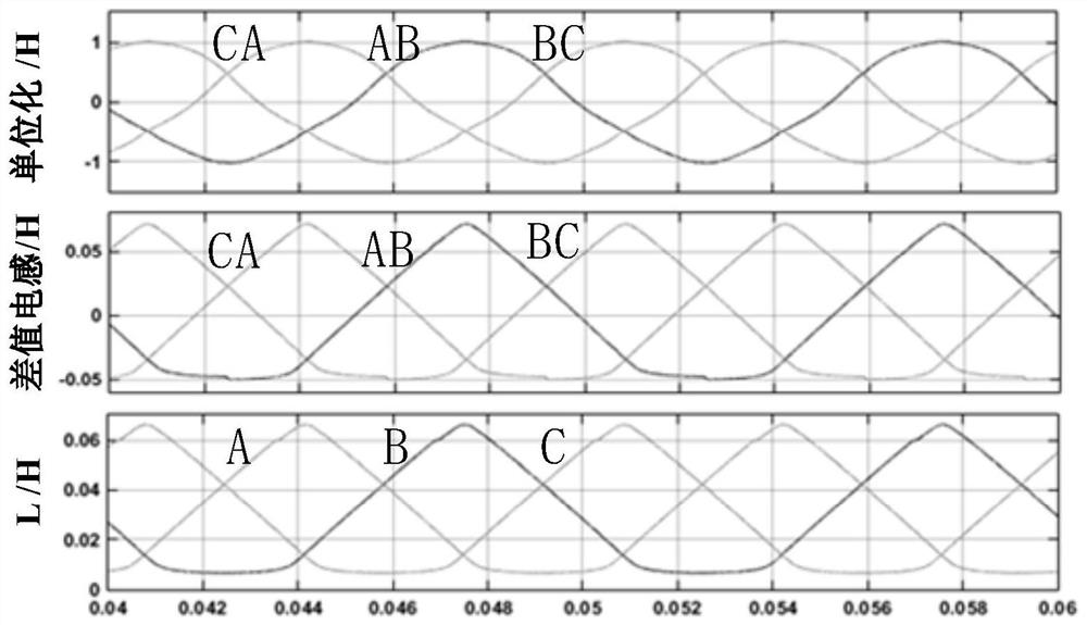
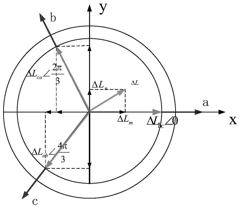
The invention discloses a switched reluctance motor sensorless method based on a difference inductance vector method, and belongs to the field of switched reluctance motor sensorless control, and the method comprises the following steps: calculating a three-phase inductance value of a switched reluctance motor in real time; delaying a three-phase inductance value expressed in a Fourier series form by pi degrees; carrying out mutual subtraction on the three-phase inductance difference values to obtain three-phase-difference-value inductance; carrying out unitization on the obtained three-phase difference value inductance; performing logic partitioning on the three-phase difference value inductor; estimating to obtain rotor position angle information at any moment in a single period by utilizing an arc tangent function and combining with three-phase difference inductance logic partitioning; according to the rotor position angle information at any moment, outputting a corresponding control signal to the switched reluctance motor to control the on and off of a power switch tube of a power converter so as to realize the sensorless control of the switched reluctance motor; the method can improve the estimation precision of the rotor position, achieves the high-precision control of the switched reluctance motor, and has a wide application prospect.

Description

technical field [0001] The invention relates to the field of positionless control of switched reluctance motors, in particular to a position sensorless method for switched reluctance motors based on a differential inductance vector method. Background technique [0002] Switched reluctance motor (switched reluctance motor, SRM) has simple structure, flexible control, high adaptability and fault tolerance due to its special double salient pole structure, concentrated winding on the stator, and no permanent magnet material and winding on the rotor. Strong and other advantages. The stable operation and high reliability of the switched reluctance motor depend on the accurate detection of the position of the motor rotor, while the traditional position information is detected by the position sensor. Because the position sensor is easily affected in some harsh environments, the position detection accuracy is not high. At the same time The installation of position sensors also incre...

Claims


Application Information

Patent Timeline
IPC IPC(8): H02P21/18H02P25/08H02P27/06
CPCH02P21/18H02P25/08H02P27/06H02P2203/09
Inventor 许爱德周丽芳程建平杨寒冰李倩妮朱景伟杨洋孙景浩
Owner DALIAN MARITIME UNIVERSITY
Learn More