Switched reluctance motor sensorless control method

A technology of switched reluctance motor and control method, applied in motor generator control, AC motor control, electronic commutation motor control, etc., can solve problems such as reducing system reliability, debugging and initial positioning workload, and increasing system cost. , to achieve the effect of reducing system cost, easy digital implementation, and improving reliability

Pending Publication Date: 2020-05-12
湖南贝加尔动力科技有限公司
View PDF0 Cites 2 Cited by
  • Summary
  • Abstract
  • Description
  • Claims
  • Application Information

AI Technical Summary

Problems solved by technology

[0003] Real-time and accurate acquisition of rotor position information is an important condition for reliable operation of switched reluctance motors, especially high-performance operation. However, in current practical engineering applications, Hall position sensors and resolvers are generally used to detect rotor positions. This increases the system cost and reduces the reliability of the system, especially the reliability of position detection in extreme environments such as high temperature and strong electromagnetic field
In addition, the debugging and initial positioning of the position sensor before normal use will also bring a certain amount of work

Method used


Image

  • Switched reluctance motor sensorless control method
  • Switched reluctance motor sensorless control method
  • Switched reluctance motor sensorless control method

Examples


Embodiment 1

[0041] Embodiment 1: Taking a three-phase 6 / 4-pole switched reluctance motor as a prototype, the steps of the position sensorless control method for the switched reluctance motor provided by the present invention are as follows:

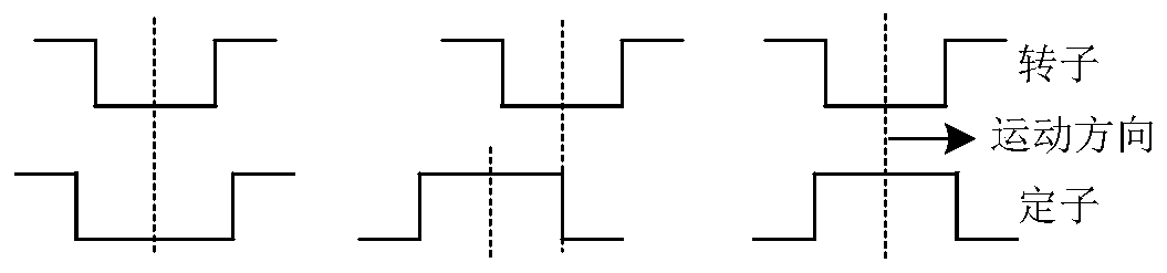
[0042] 1) Use the current slope difference method to measure the value of the phase incremental inductance of the prototype under different phase currents at the position where the rotor and the stator poles are completely aligned, where the rotor pole edge is aligned with the stator pole center, and where the rotor pole is completely aligned with the stator groove center . The formula for estimating the phase increment inductance by the current slope difference method is:

[0043]

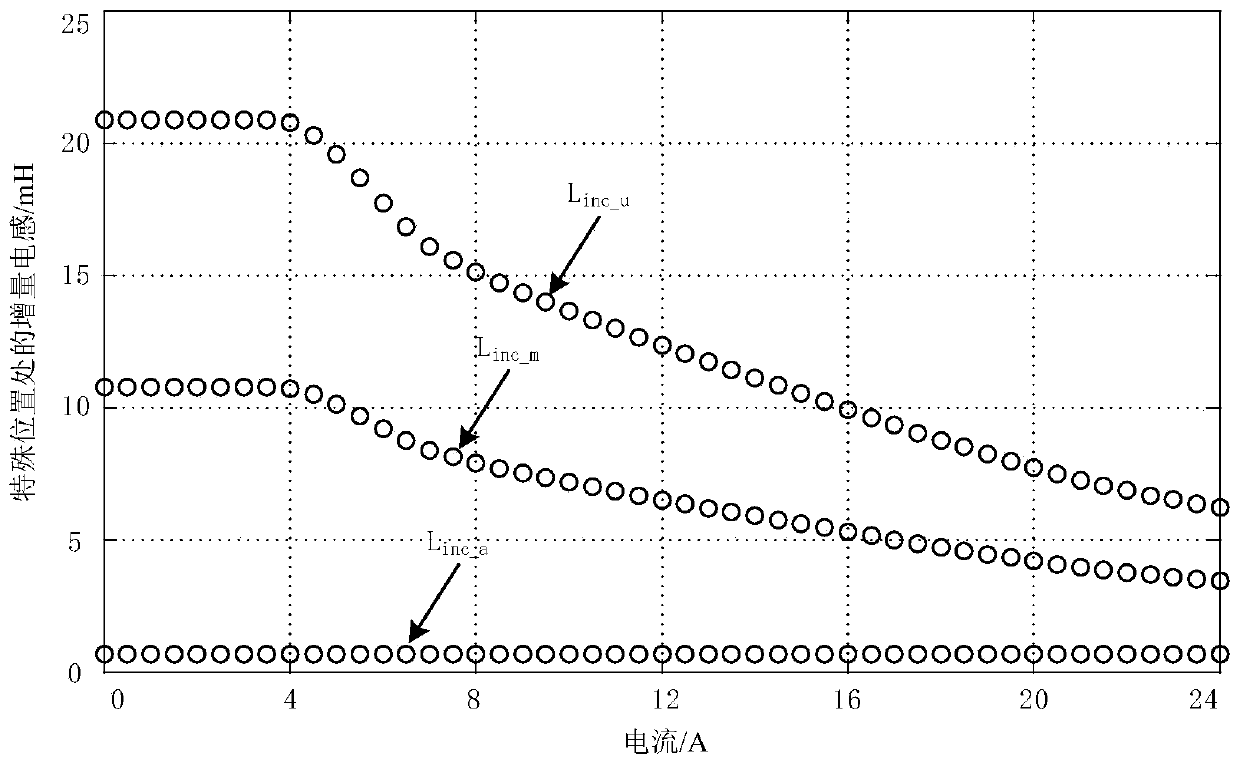
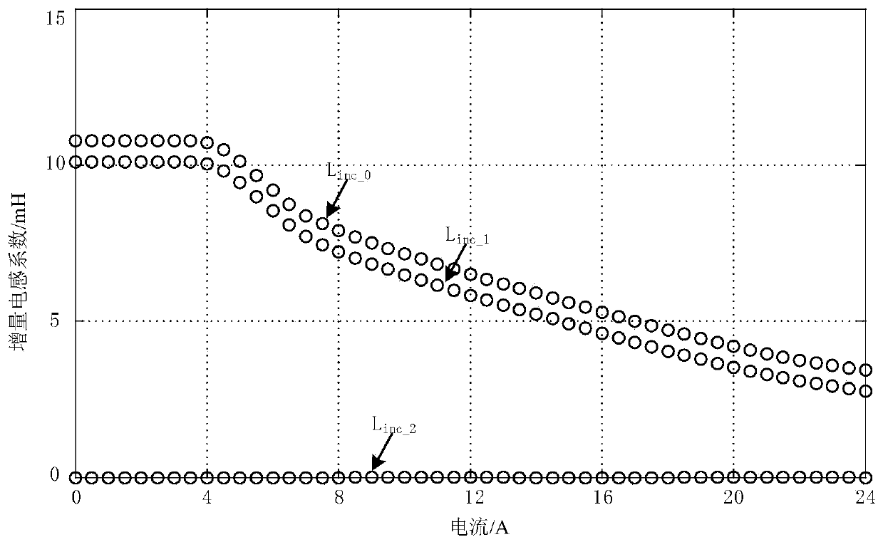
[0044] The three positions are the three special positions of each phase incremental inductance, as attached figure 1 shown. The curves of the prototype phase incremental inductance changing with the phase current at three special positions are attached figure 2 s...


PUM


Abstract

The invention belongs to the field of motor control, and particularly relates to a switched reluctance motor sensorless control method. The method comprises: establishing a simplified incremental inductance model based on the simplified Fourier series expression of switched reluctance motor inductance and the relational expression of incremental inductance and inductance; measuring the incrementalinductances of three special rotor positions of a switched reluctance motor under different phase currents so as to obtain a relation that an incremental inductance model coefficient changes along with the phase currents, and establishing the nonlinear incremental inductance model of the switched reluctance motor; deducing an analytic expression for estimating the rotor position of the switched reluctance motor according to the phase increment inductance and the coefficient thereof according to the increment inductance model; and when the motor operates, detecting phase current and bus voltage, estimating excitation phase increment inductance by adopting a current slope difference method, calculating the current rotor position by utilizing the derived rotor position analytical formula, and achieving the sensorless operation control of the switched reluctance motor according to the estimated rotor position. The control method is simple, small in calculation amount, easy to realize digitalization and high in position estimation precision.

Description

technical field [0001] The invention relates to a method for controlling a switched reluctance motor, in particular to a method for controlling a switched reluctance motor without a position sensor based on an incremental inductance model. Background technique [0002] Switched reluctance motor is a new type of electromechanical integration motor, which has the advantages of simple and firm structure, reliable operation, good speed regulation performance, low manufacturing cost, suitable for high speed and harsh environment operation, etc. These excellent characteristics make it an electrical One of the research topics in the field of transmission, it has been applied in the fields of motor drive systems, fans, water pumps, aerospace and other fields, showing its strong market competitiveness. [0003] Real-time and accurate acquisition of rotor position information is an important condition for reliable operation of switched reluctance motors, especially high-performance op...

Claims


Application Information

Patent Timeline
Patent Type & Authority Applications(China)
IPC IPC(8): H02P21/18H02P25/089
CPCH02P21/18H02P25/089
Inventor 李孟秋蔡辉沈仕其
Owner 湖南贝加尔动力科技有限公司
Why Eureka
Try Eureka