
Switchgear assembly, and submersible electrical enclosure and method of manufacturing a submersible electrical enclosure therefor

a technology of submersible electrical enclosures and electrical switching apparatuses, which is applied in the direction of substations, non-enclosed substations, and arrangement with resin casings, etc., can solve the problems of affecting the operation of substations. , the submerged electrical enclosure is sensitive to leakage, and the enclosure is expensive to fabrica

Active Publication Date: 2016-05-12
EATON INTELLIGENT POWER LIMITED
View PDF10 Cites 5 Cited by
  • Summary
  • Abstract
  • Description
  • Claims
  • Application Information

AI Technical Summary

Benefits of technology

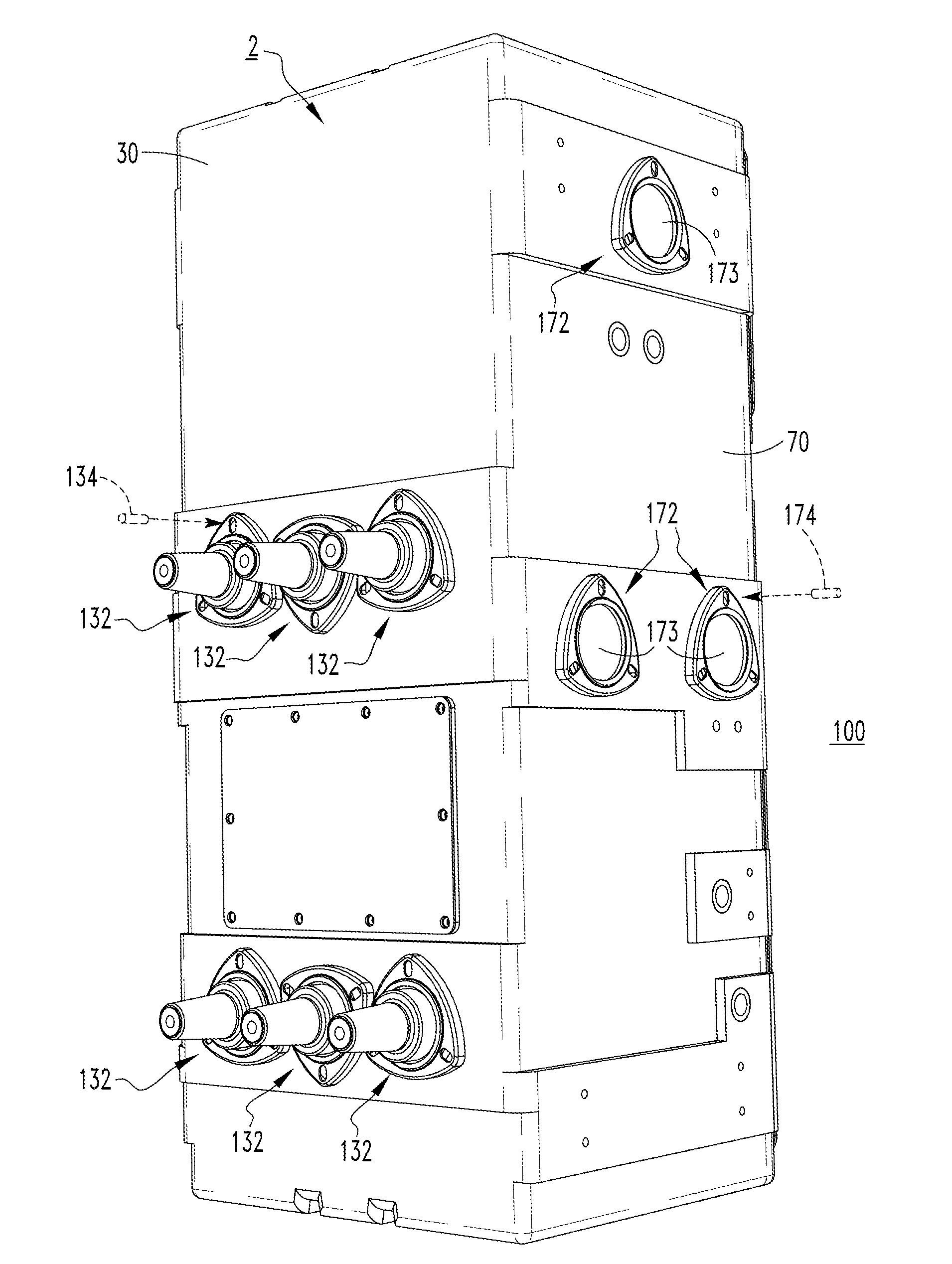
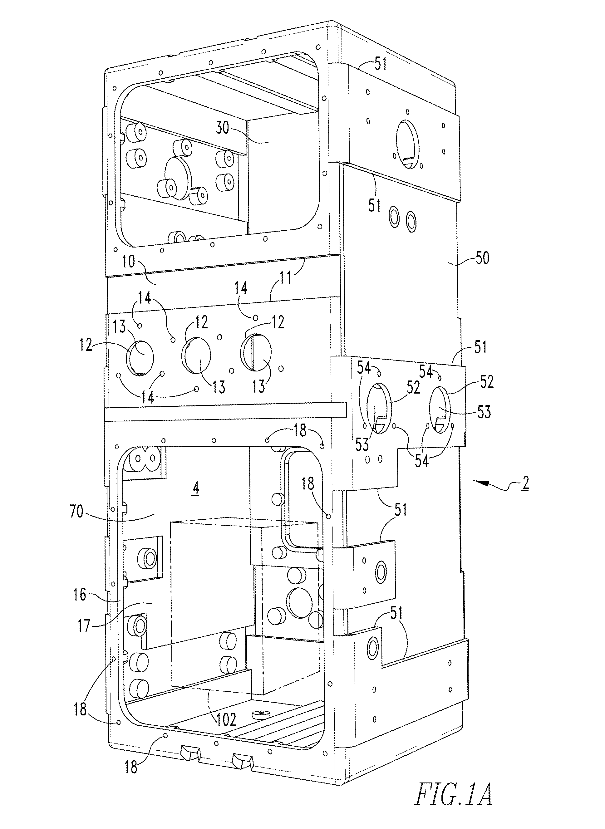
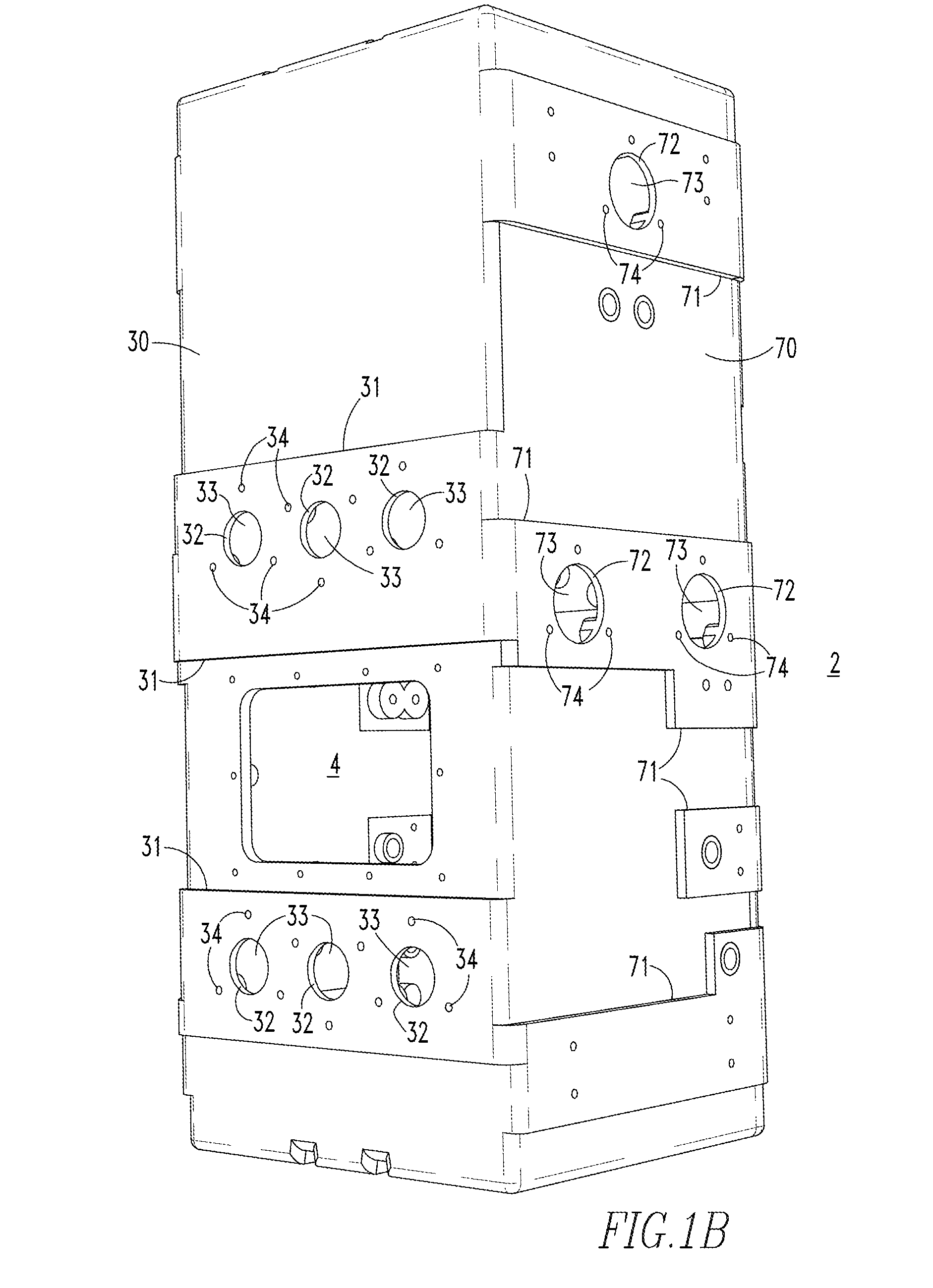
The disclosed concept is about a switchgear assembly and a submersible electrical enclosure. The submersible electrical enclosure has a conductive polymeric layer and an insulative polymeric layer that helps protect the electrical switching apparatus from water intrusion. The switchgear assembly includes the electrical switching apparatus and the submersible electrical enclosure. The manufacturing method involves applying a predetermined amount of conductive material and insulative material to a mold and then removing the materials from the mold. Overall, the disclosed concept provides a more reliable and durable solution for protecting electrical equipment in water-dependent environments.

Problems solved by technology

In operation, such electrical switching apparatus are often exposed to moisture, sewage, dirt, small animals, and other contaminants.
However, such enclosures are expensive to fabricate, heavy, and sensitive to leaks as a result of necessary welds.
Additionally, a known drawback with such stainless steel submersible electrical enclosures is condensation.

Method used


Image

  • Switchgear assembly, and submersible electrical enclosure and method of manufacturing a submersible electrical enclosure therefor
  • Switchgear assembly, and submersible electrical enclosure and method of manufacturing a submersible electrical enclosure therefor
  • Switchgear assembly, and submersible electrical enclosure and method of manufacturing a submersible electrical enclosure therefor

Examples


Embodiment Construction

[0023]As employed herein, the term “number” shall mean one or an integer greater than one (i.e., a plurality).

[0024]As employed herein, the statement that two or more parts are “connected” or “coupled” together shall mean that the parts are joined together either directly or joined through one or more intermediate parts.

[0025]As employed herein, the statement that two or more parts or components “engage” one another shall mean that the parts touch and / or exert a force against one another either directly or through one or more intermediate parts or components.

[0026]As employed herein, the term “coupling member” refers to any suitable connecting or tightening mechanism expressly including, but not limited to, rivets, screws, bolts and the combinations of bolts and nuts (e.g., without limitation, lock nuts) and bolts, washers and nuts.

[0027]As employed herein, the term “conductive polymeric layer” or “conductive polymeric material” shall mean a polymeric material, such as high density ...


PUM

PropertyMeasurementUnit
surface resistivityaaaaaaaaaa
dielectric strengthaaaaaaaaaa
conductiveaaaaaaaaaa

Abstract

A submersible electrical enclosure is for a switchgear assembly. The switchgear assembly includes a number of electrical switching apparatus. The submersible electrical enclosure includes: a plurality of sides defining an interior, the interior receiving each of the electrical switching apparatus, each side including: a conductive polymeric layer facing away from the interior, and an insulative polymeric layer molded to the conductive polymeric layer. The insulative polymeric layer faces the interior and substantially overlays the conductive polymeric layer.

Description

CROSS REFERENCE TO RELATED APPLICATION[0001]This application claims the benefit of U.S. Provisional Patent Application Ser. No. 62 / 078,082, filed Nov. 11, 2014, which is incorporated by reference herein.BACKGROUND[0002]1. Field[0003]The disclosed concept pertains generally to switchgear assemblies and, more particularly, to switchgear assemblies including for example, electrical switching apparatus. The disclosed concept also pertains to submersible electrical enclosures for switchgear assemblies. The disclosed concept further pertains to methods of manufacturing submersible electrical enclosures.[0004]2. Background Information[0005]Electrical switching apparatus, such as medium voltage switching apparatus (e.g., without limitation, air switches, vacuum circuit breakers, loadbreak switches and non-loadbreak switches), provide protection for electrical systems from electrical fault conditions, such as current overloads, short circuits, abnormal voltage and other fault conditions. In ...

Claims


Application Information

Patent Timeline
Patent Type & Authority Applications(United States)
IPC IPC(8): H02B1/28B29C70/88B29C70/72B29C70/68H02B13/01H02B1/48
CPCH02B1/28H02B13/01H02B1/48B29C70/72B29C70/681B29C70/882B29L2031/3481B29K2105/16B29K2995/0005B29K2995/0007B29K2995/0069B29L2009/00B29K2023/065H02B1/40H01L23/3107H01L23/49548
Inventor FAULKNER, MARKPEARCE, MICHAEL DAVISSPOONE, TRAVIS
Owner EATON INTELLIGENT POWER LIMITED
Learn More