
MIMO communication system for propagation environment including deterministic communication channel, and antennas for MIMO communication system

a communication system and propagation environment technology, applied in the field of space division multiplexing system, to achieve the effect of reducing the spacing between antennas

Active Publication Date: 2016-05-12
NEC CORP
View PDF4 Cites 8 Cited by
  • Summary
  • Abstract
  • Description
  • Claims
  • Application Information

AI Technical Summary

Benefits of technology

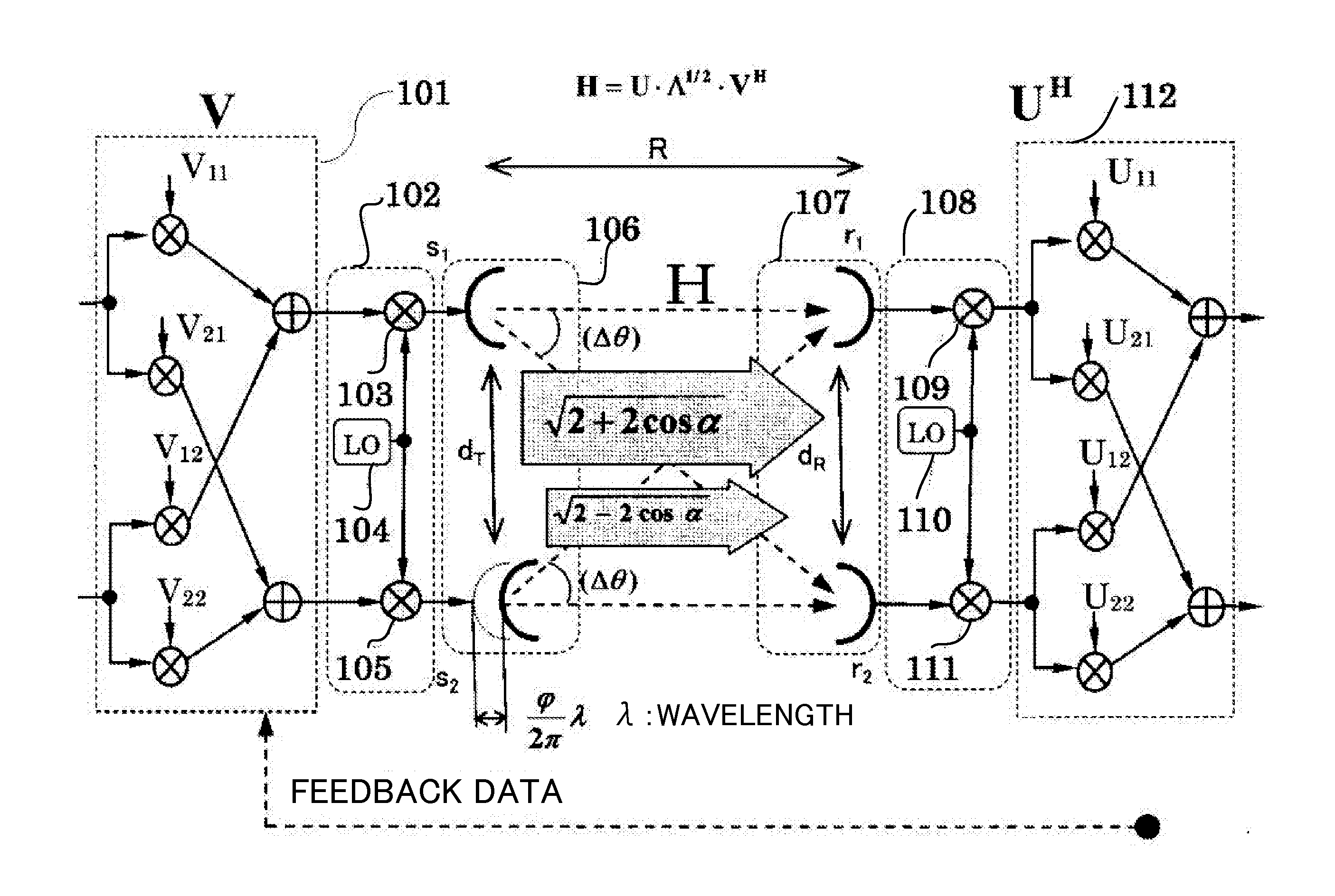
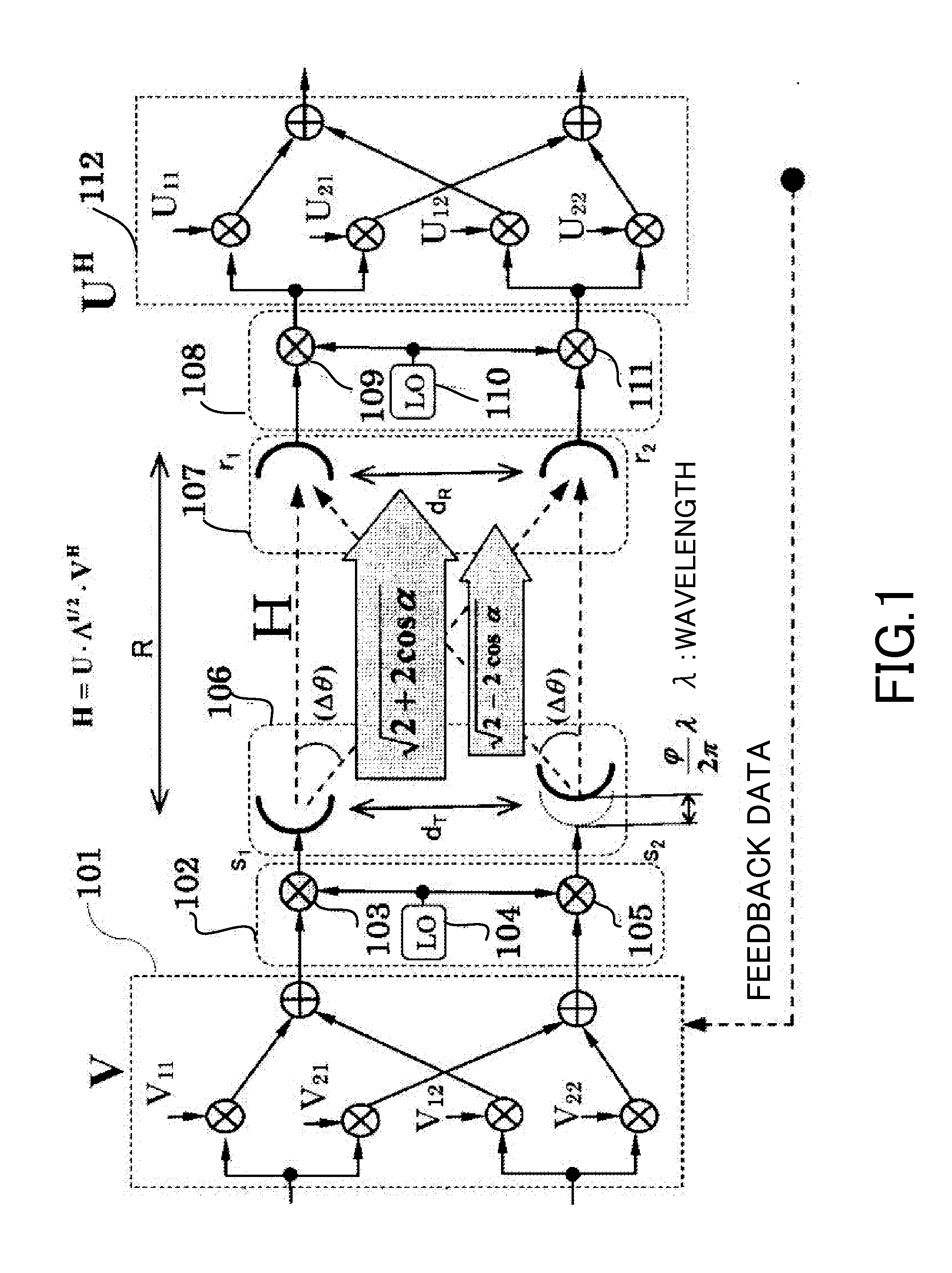
The patent invention relates to a communication system where two antennas can communicate with each other through a straight line of sight. The invention allows for a shorter distance between the antennas, either at the transmitting side or the receiving side, or both. This reduces the space required for the antennas and improves the efficiency of the communication.

Problems solved by technology

In other words, the problem with the carrier synchronization among the antennas becomes large constraint to construct the fixed microwaves communication system.

Method used


Image

  • MIMO communication system for propagation environment including deterministic communication channel, and antennas for MIMO communication system
  • MIMO communication system for propagation environment including deterministic communication channel, and antennas for MIMO communication system
  • MIMO communication system for propagation environment including deterministic communication channel, and antennas for MIMO communication system

Examples


example

[0324]As a simple example, the above formula is applied to the arrangement with two antennas.

As the fixed arbitrary transmission matrix, for instance, the following formula 124 is selected.

V=[-1212-12-12]{Formula124}

[0325]Based on the following formula 125, the following formula 126 is established.

H0=[1-j-j1]{Formula125}UH=VHN·TH·HoH·WH=[-12-1212-12]·[100-jΦ1]·[1jj1]·[100-jφ1]=[-1-j-jΦ12-j-jφ1-j-j(Φ1+φ1)21-j-jΦ12j-jφ1-j-j(Φ1+φ1)2]{Formula126}

[0326]Hereafter, the orthogonal relation adopted in the above formula 114 is explained as follows.


PUM


Abstract

In a MIMO communication system that includes a transmitter and a receiver and forms line-of-sight orthogonal channels between the transmitter-side transmitting antenna and the receiver-side receiving antenna, the MIMO communication system is provided between the transmitting antenna and the receiving antenna with an optimum antenna-to-antenna spacing shortening unit to shorten an optimum antenna-to-antenna spacing by changing the phase rotation of a carrier wave used for directly opposed waves between opposed antennas, and the phase rotation of a carrier wave used for intersecting waves between oblique antennas in such a manner that the amount by which one of the phase rotations changes is different from that by which the other phase rotation changes.

Description

TECHNICAL FIELD[0001]The present invention relates to a space division multiplexing system (hereinafter, referred to as MIMO; Multiple-Input / Multiple-Output), particularly, pertaining to an MIMO communication system adopted for a fixed microwaves communication system in the line-of-sight communication system, a mobile communication system in which the line-of-sight propagation is included even under the propagation environment entailing reflections and scatterings and the propagation environment in which the line-of-sight propagation is included indoor and to antennas for such MIMO communication system.BACKGROUND ART[0002]In the wireless communication, the communication system adopting such MIMO has prevailed over the relevant market, so that the MIMO itself comes to be no novel to the persons skilled in the art. However, the communication system adopting the MIMO has been centered on a mobile communication, but has not been applied for a fixed communication to date. With the radio ...

Claims


Application Information

Patent Timeline
IPC IPC(8): H04B7/04H04L5/00
CPCH04L5/0048H04B7/0456
Inventor MARU, TSUGUO
Owner NEC CORP
Learn More