Vehicle seat

a seat cushion and seat technology, applied in the field of vehicle seats, can solve the problems of affecting the safety of pedestrians/occupants, affecting the seat cushion and the floor, and destroying the lower portion of the seat cushion and the floor, and achieve the effect of reducing the number of reinforcing members and simple structur

Active Publication Date: 2016-05-19
TOYOTA BOSHOKU KK
View PDF6 Cites 5 Cited by
  • Summary
  • Abstract
  • Description
  • Claims
  • Application Information

AI Technical Summary

Benefits of technology

[0015]According to the above configuration, by using the reinforcing member having a simple structure, it is possible to efficiently cause the reinforcing

Problems solved by technology

However, in the case where the slide rails are coupled to each other using the reinforcing member, when a side collision occurs in the vehicle, a compression load that is larger than that at the time of the rear-end collision is applied to the reinf

Method used


Image

  • Vehicle seat
  • Vehicle seat
  • Vehicle seat

Examples


Embodiment Construction

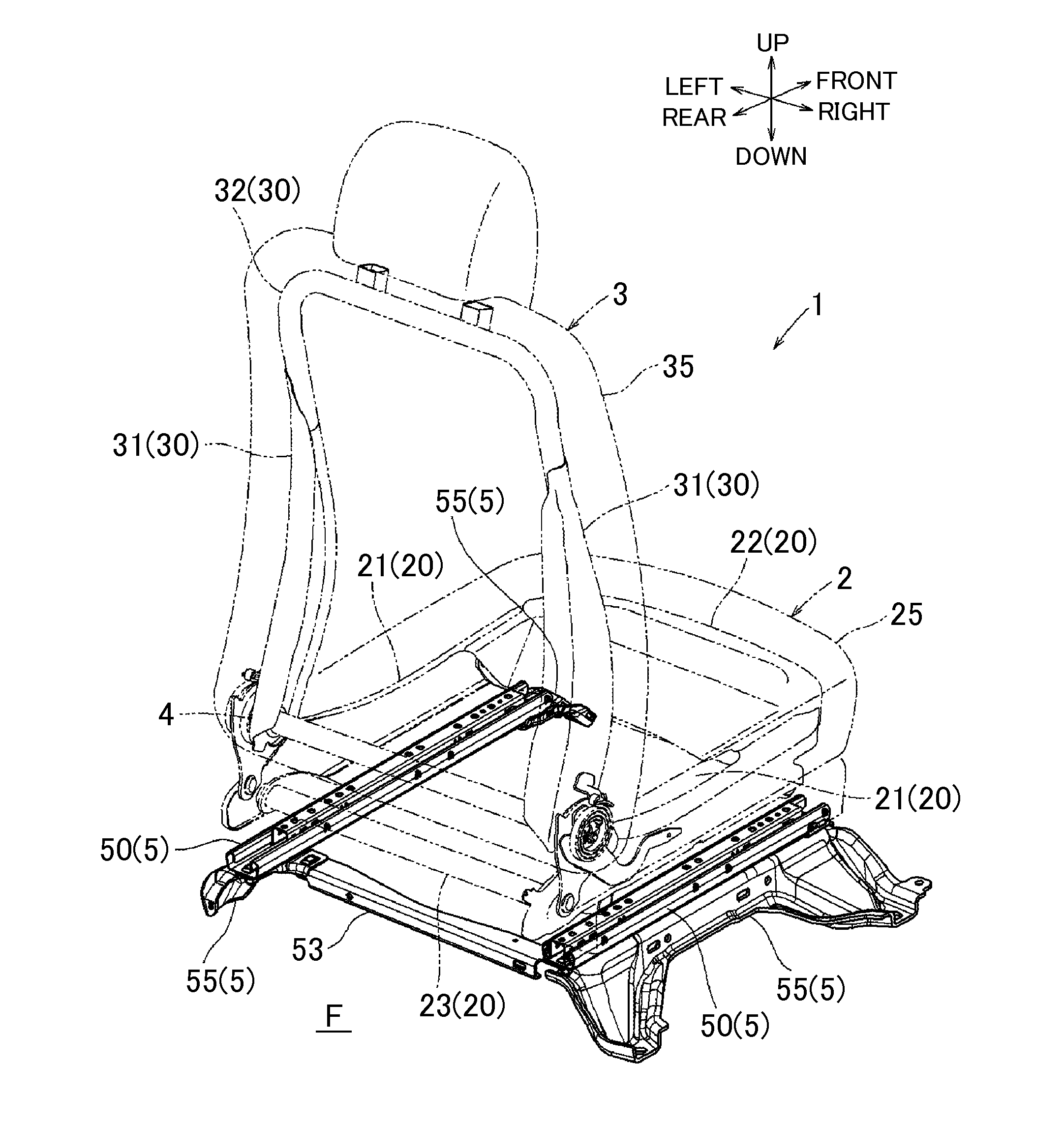
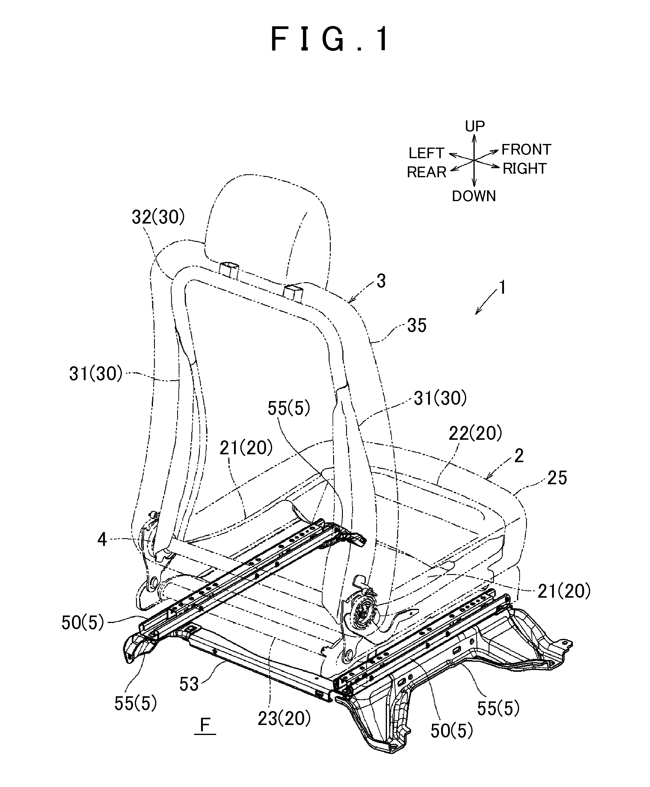
[0027]FIGS. 1 to 10 show an embodiment of the invention. The embodiment shows an example in which the invention is applied to a vehicle seat. In each of the drawings, individual directions of a vehicle when the vehicle seat is mounted to the vehicle are indicated by arrows. In the following description, the description related to directions is assumed to be made based on the directions.

[0028]As shown in FIG. 1, a vehicle seat 1 of the present embodiment includes a seat cushion 2, a seat back 3, and a slide mechanism 5 that supports the seat cushion 2 to a floor F such that the seat cushion 2 is slidable in a front and rear direction. Lower end portions of the seat back 3 on both sides are coupled to rear end portions of the seat cushion 2 via recliners 4. Each recliner 4 performs a function of adjusting a tilt angle of the seat back 3 with respect to the seat cushion 2. Herein, the seat cushion 2 and the seat back 3 are an example of a “seat main body” of CLAIMS.

[0029]The seat cushi...


PUM


Abstract

A vehicle seat includes a pair of left and right slide rails each having a lower rail extending in a front and rear direction of a vehicle and an upper rail slidably mounted to the lower rail. The lower rail is fixed to a floor F via brackets and so as to be spaced apart from the floor F. A reinforcing member extending in a left and right direction is disposed so as to span between rear end portions of the lower rails, and the reinforcing member is formed such that a bending strength about an axis in an up and down direction of a seat main body is lower than a bending strength about an axis in a front and rear direction of the seat main body.

Description

INCORPORATION BY REFERENCE[0001]The disclosure of Japanese Patent Application No. 2014-231530 filed on Nov. 14, 2014 including the specification, drawings and abstract is incorporated herein by reference in its entirety.BACKGROUND OF THE INVENTION[0002]1. Field of the Invention[0003]The invention relates to a vehicle seat.[0004]2. Description of Related Art[0005]When a rear-end collision occurs in a state in which a vehicle seat is mounted to a vehicle floor in an orientation that causes a seated passenger to face the front of a vehicle, a force that tilts a seat back rearward is applied to the vehicle seat. The force is transmitted to a seat cushion via a recliner, and is further transmitted from the seat cushion to a pair of slide rails as a force that pushes down rear portions of the slide rails. Herein, when a bracket that supports the pair of the slide rails to a floor falls in a left and right direction due to the action of a component force of the above pushing-down force in ...

Claims


Application Information

Patent Timeline
IPC IPC(8): B60N2/50B60N2/07
CPCB60N2/509B60N2/502B60N2/073B60N2/015B60N2/0705B60N2/4228B60N2/4235B60N2/42709
Inventor NAGATA, HIROKITANAKA, TETSUYAISHII, SHOGOISSHIKI, KAZUHISAOKAZAKI, YUICHISAITO, KEIICHI
Owner TOYOTA BOSHOKU KK
Why Eureka
Try Eureka