Whole-body human-computer interface

a human-computer interface and whole-body technology, applied in the field of virtual reality human-computer interfaces, can solve the problems of no known human-computer interface device yet to come close to achieving, limited general applicability, and little change in the commercial landscape of human-computer interfaces

Active Publication Date: 2016-05-19
HAPTX INC
View PDF5 Cites 303 Cited by
  • Summary
  • Abstract
  • Description
  • Claims
  • Application Information

AI Technical Summary

Problems solved by technology

However, despite the rapid evolution of software capabilities, the commercial landscape of human-computer interfaces has changed little since the dawn of the personal computing era.
No known human-computer interface device has yet come close to achieving the long-held goal of enabling fully immersive (i.e. natural, full-body, and pan-sensory) interaction with a computerized environment.
These systems employ simplified simulation parameters to achieve a design that is conducive to their particular application, but are severely limited in general applicability.
Such a design methodology tends to reduce mechanical and computational complexity for many tasks, but at the cost of compromising flexibility, adaptability, and economy of scale of the resultant systems.
Such a design is antithetical to natural simulation

Method used


Image

  • Whole-body human-computer interface
  • Whole-body human-computer interface
  • Whole-body human-computer interface

Examples


first embodiment

[0129]The proximal boundary 450 of opisthenar structural member 412 is preferably delimited approximately by the radial styloid process of the wearer's wrist. Distal boundary 452 is preferably delimited approximately by the proximal edge of the metacarpophalangeal joints of the wearer's second through fifth metacarpals. Medial and lateral boundaries of opisthenar structural member 412 are preferably delimited approximately by the outside edges of the wearer's second and fifth metacarpal respectively. In one embodiment, an opisthenar structural member 412 comprises a length adjustment mechanism (not shown), preferably located near wrist joint 419a. In a first embodiment, a hand segment 204a / b (FIG. 2) of an exoskeleton comprises an opisthenar structural member 412 and a means of securing the opisthenar structural member 412 to the wearer's hand (not shown in FIGS. 4A-4B). Said means can, for example, comprise a strap, band, glove, brace, or similar element.

second embodiment

[0130]Referring now to FIG. 9, a hand segment 204a / b is shown. Opisthenar structural member 412 is coupled to thumb proximal phalangeal structural member 920 via thumb metacarpophalangeal joint 939. Thumb metacarpophalangeal joint 939 preferably comprises two pin-type revolute articulations 942 and 944, whose compound motion emulates flexion / extension and abduction / adduction of the metacarpophalangeal joint of the wearer's thumb. Articulation 934 is coupled to articulation 942 via an arc-shaped structural member 919. Arc-shaped structural member 919 is preferred to be shaped so as to project as little as possible from the hand of the wearer without limiting the range of motion of the wearer or the exoskeleton.

[0131]Thumb proximal phalangeal structural member 920 is coupled to thumb intermediate phalangeal structural member 922 via thumb proximal interphalangeal joint 935. Thumb proximal interphalangeal joint 935 preferably comprises one or more pin-type articulations 936, 937 having...

third embodiment

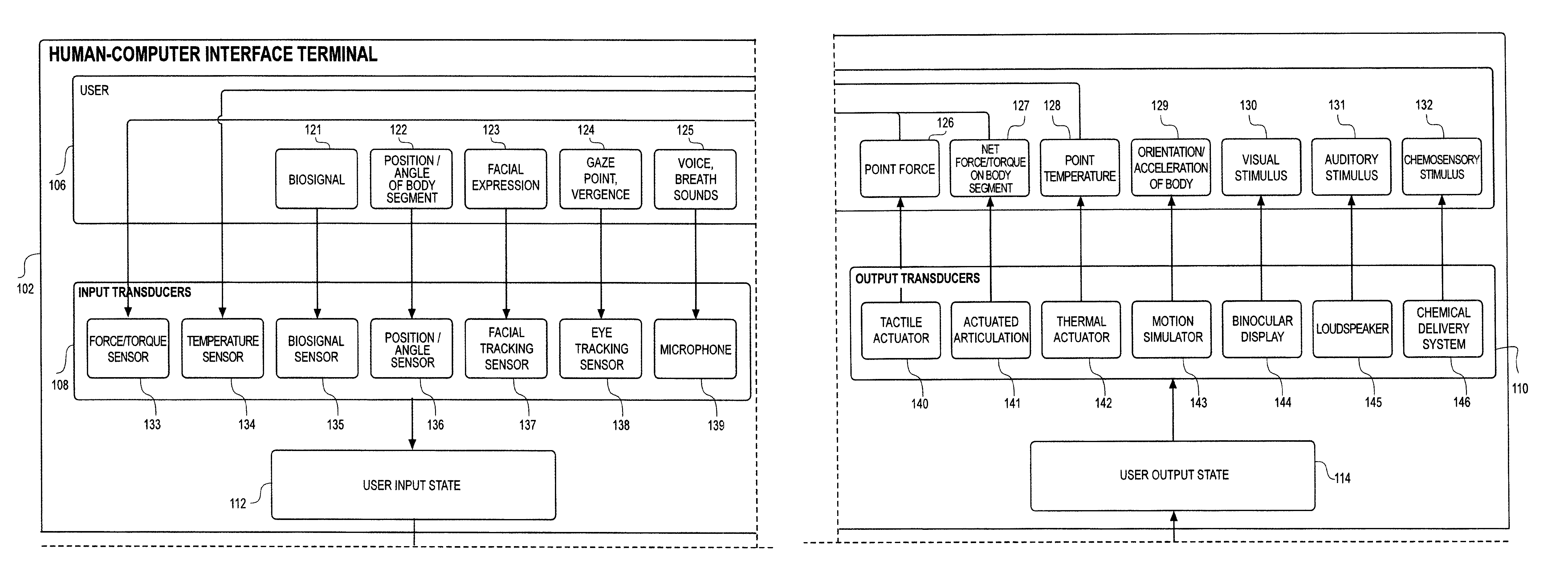
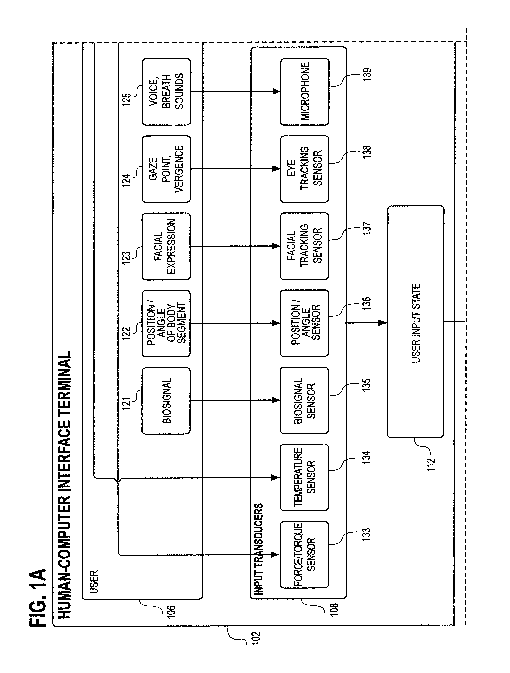
[0134]In a hand segment 204a / b (FIG. 2), a device is provided to be held in the wearer's hand. Said device is preferably coupled to opisthenar structural member 412 (FIGS. 4A-4B). In one variation, said device comprises a controller, such as a game controller. This controller preferably comprises at least one input transducer, such as a button, which can be used to provide input to a computer-mediated environment process 116 (FIG. 1). In another variation, said hand-held device comprises a “prop,” such as a gun, sword, or medical instrument that represents a corresponding article in a computer-mediated environment process 116 (FIG. 1). This prop likewise optionally comprises one or more input transducers, such as a trigger, which can be used to provide input to a computer-mediated environment process 116 (FIG. 1). In an additional variation, said hand-held device comprises a handle or other stiff projection that can be enclosed by the hand of the wearer.


PUM


Abstract

A human-computer interface system having an exoskeleton including a plurality of structural members coupled to one another by at least one articulation configured to apply a force to a body segment of a user, the exoskeleton comprising a body-borne portion and a point-of-use portion; the body-borne portion configured to be operatively coupled to the point-of-use portion; and at least one locomotor module including at least one actuator configured to actuate the at least one articulation, the at least one actuator being in operative communication with the exoskeleton.

Description

[0001]This application is a continuation of International Application No. PCT / US14 / 44735, filed Jun. 27, 2014, which claims the benefit of Provisional Application No. 61 / 843,317 filed Jul. 5, 2013.BACKGROUND OF THE INVENTION[0002]1. Field of the Invention[0003]The present invention relates generally to virtual reality human-machine interfaces, and more specifically to immersive virtual reality human-machine interfaces. Even more specifically, the present invention relates to immersive virtual reality human-machine interfaces with auditory, visual, proprioceptive, mechanoreceptive, thermoreceptive, and equilibrioceptive modalities.[0004]2. Discussion of the Related Art[0005]Virtual reality systems are computer-based systems that provide experiences to a participant acting in a simulated environment that forms a three dimensional virtual world. These systems are used in several different applications such as commercial flight simulators, entertainment systems, computer games and video...

Claims


Application Information

Patent Timeline
IPC IPC(8): G06F3/01G06T19/00G09B9/00G06F3/16A63F13/212
CPCG06F3/013G06F3/014G06F3/162G06T19/006A63F13/212G09B9/00G06F3/015B25J11/003A61H1/024A61H1/0244A61H1/0266A61H1/0277A61H1/0281A61H1/0285A61H3/00B25J9/0006A61H2003/063A61H2201/0165A61H2201/0228A61H2201/5007A61H2201/5043A61H2201/5061A61H2201/5069A61H2201/5084A61H2201/5092A63F13/98A63F13/21A63F13/24A63F13/285G06F3/011G06F3/012G06F3/016
Inventor RUBIN, JACOB A.CROCKETT, ROBERT S.
Owner HAPTX INC
Why Eureka
Try Eureka