Wiring structure for electroacoustic transducer for digital signal and headphone for digital signal

a technology of electroacoustic transducers and headphones, applied in the direction of earpiece/earphone cables, loudspeakers, earpiece/earphone manufacture/assembly, etc., can solve the problems of inability to achieve high-quality sound, receive uncorrected digital signals including extraneous noise, etc., and achieve high-quality sound waves.

Active Publication Date: 2016-05-19
AUDIO-TECHNICA
View PDF8 Cites 19 Cited by
  • Summary
  • Abstract
  • Description
  • Claims
  • Application Information

AI Technical Summary

Benefits of technology

[0017]The present invention can prevent extraneous noise from invading into the connecting cables between the paired right and l

Problems solved by technology

The received uncorrected digital signals include extraneous noise, which has invaded through the connecting cable.
Although digital signals generally have high noise resistance, digital signals affected by extraneous noise and uncorrected at the receiver may fail to produce high-quality sound.
Such traditional solution

Method used


Image

  • Wiring structure for electroacoustic transducer for digital signal and headphone for digital signal
  • Wiring structure for electroacoustic transducer for digital signal and headphone for digital signal
  • Wiring structure for electroacoustic transducer for digital signal and headphone for digital signal

Examples


Embodiment Construction

[0023]With reference to the drawings, embodiments of the wiring structure and electroacoustic transducer of the present invention will now be described.

Electroacoustic Transducer

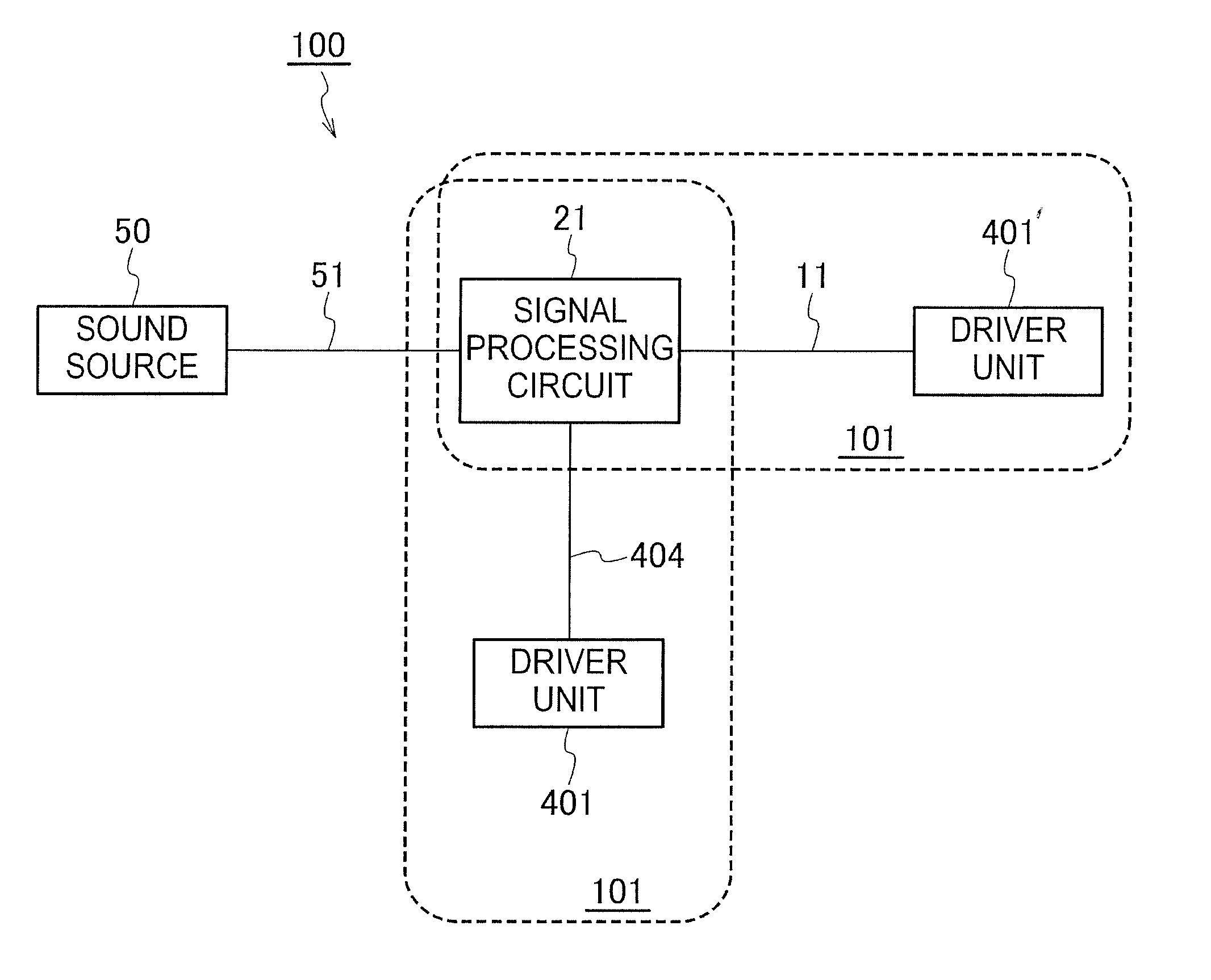
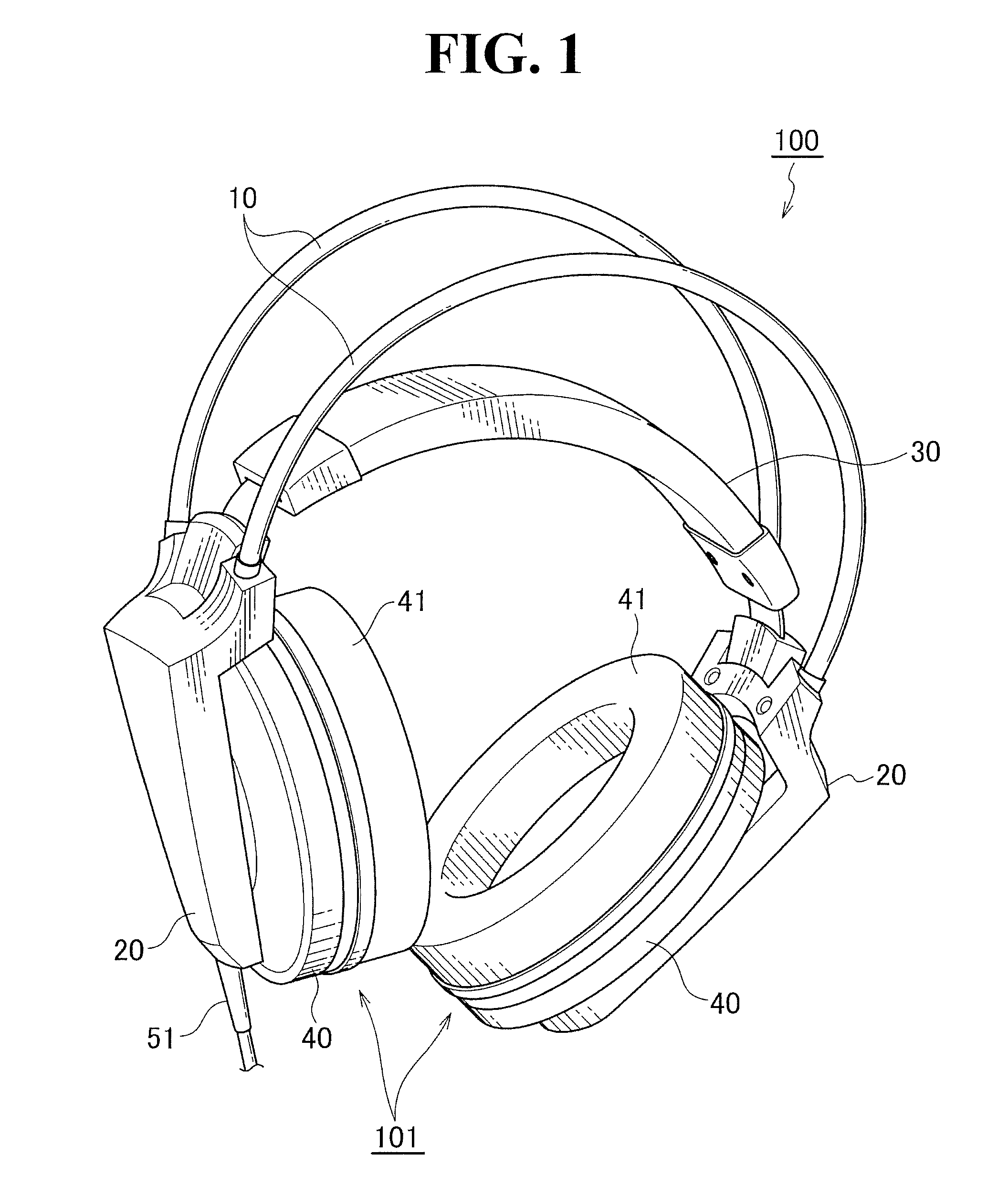
[0024]An embodiment of the electroacoustic transducer will be described. As shown in FIG. 1, a headphone assembly 100 includes a pair of right and left ear pieces or headphone units 101, each having an electroacoustic transducer. The headphone units 101 are held by supports 20 connected to two ends of a head pad 30. Each headphone unit 101 includes an ear pad 41 to be worn by a user on his ear, and a housing 40 on which the ear pad 41 is mounted. The contact face of the ear pad 41 is substantially oval so as to cover a use's ear. The housing 40 is also substantially oval conforming to the ear pad 41. The housing 40 and the ear pad 41 may have any shape other than the substantially oval shape. For example, the shape may be a substantially circular shape, which has been traditionally employed, or a polygonal s...


PUM


Abstract

A wiring structure is provided for an electroacoustic transducer directly converting digital signals from a single sound source to sound waves without conversion to analogue signals. The structure includes a diaphragm, and a plurality of voice coils fixed to the diaphragm. The voice coils are connected to respective cables each consisting of a stranded pair of positive and negative input lines.

Description

TECHNICAL FIELD[0001]The present invention relates to a wiring structure for an electroacoustic transducer and a headphone.BACKGROUND ART[0002]A traditional electroacoustic transducer for use in an audio speaker or a headphone assembly includes a diaphragm vibrating in response to the magnitude and frequency of input analogue signals for generating sound waves. Digital signals from a sound source should be converted into analogue signals before input to the traditional electroacoustic transducer.[0003]A signal converter has been developed that enables an electroacoustic transducer to receive digital signals from a sound source without conversion of the digital signals into analogue signals and drive a diaphragm vibrating in response to the compression or density of digital signals for generating sound waves (See for example PTL 1: Japanese Patent No. 4,883,428).[0004]A headphone assembly including the signal converters disclosed in PTL 1 in a right ear piece and a left ear piece can...

Claims


Application Information

Patent Timeline
IPC IPC(8): H04R1/10H04R9/04
CPCH04R9/04H04R1/1033H04R1/005H04R1/1066H04R9/063H04R1/1008H04R5/0335H04R2201/103H04R2209/022
Inventor TANOUE, KOICHIROTSUIHIJI, KENZOHONDA, YOJIARAI, KENJI
Owner AUDIO-TECHNICA
Why Eureka
Try Eureka