Tool clamping system

a clamping system and tool technology, applied in the field of tool clamping system, can solve the problems of limiting variables such as energy supply through batteries or accumulators, additional maintenance and supervision effort, and limitation of actuator systems, so as to facilitate axial movement of inertial mass, effective energy recovery, and large magnetic detent moment

Inactive Publication Date: 2016-05-26
OTTO BILZ WERKZEUGFAB
View PDF7 Cites 2 Cited by
  • Summary
  • Abstract
  • Description
  • Claims
  • Application Information

AI Technical Summary

Benefits of technology

[0033]A large magnetic detent moment is thus avoided and an axial movement of the inertial mass is facilitated.
[0034]As a result of these measures, a very effective energy recovery can be ensured.

Problems solved by technology

However, the supply by means of battery or accumulator is usually a limiting variable, since the assurance of the energy supply thus leads to additional maintenance and supervision effort.
In addition, the energy supply in the case of sensor systems or possibly also actively operating, actuator systems generally constitutes a limitation.
As a result, and due to the extremely harsh environment in the working area of machine tools, the equipping of tools known per se with additional intelligence is not successful in principle.

Method used


Image

  • Tool clamping system
  • Tool clamping system
  • Tool clamping system

Examples


Embodiment Construction

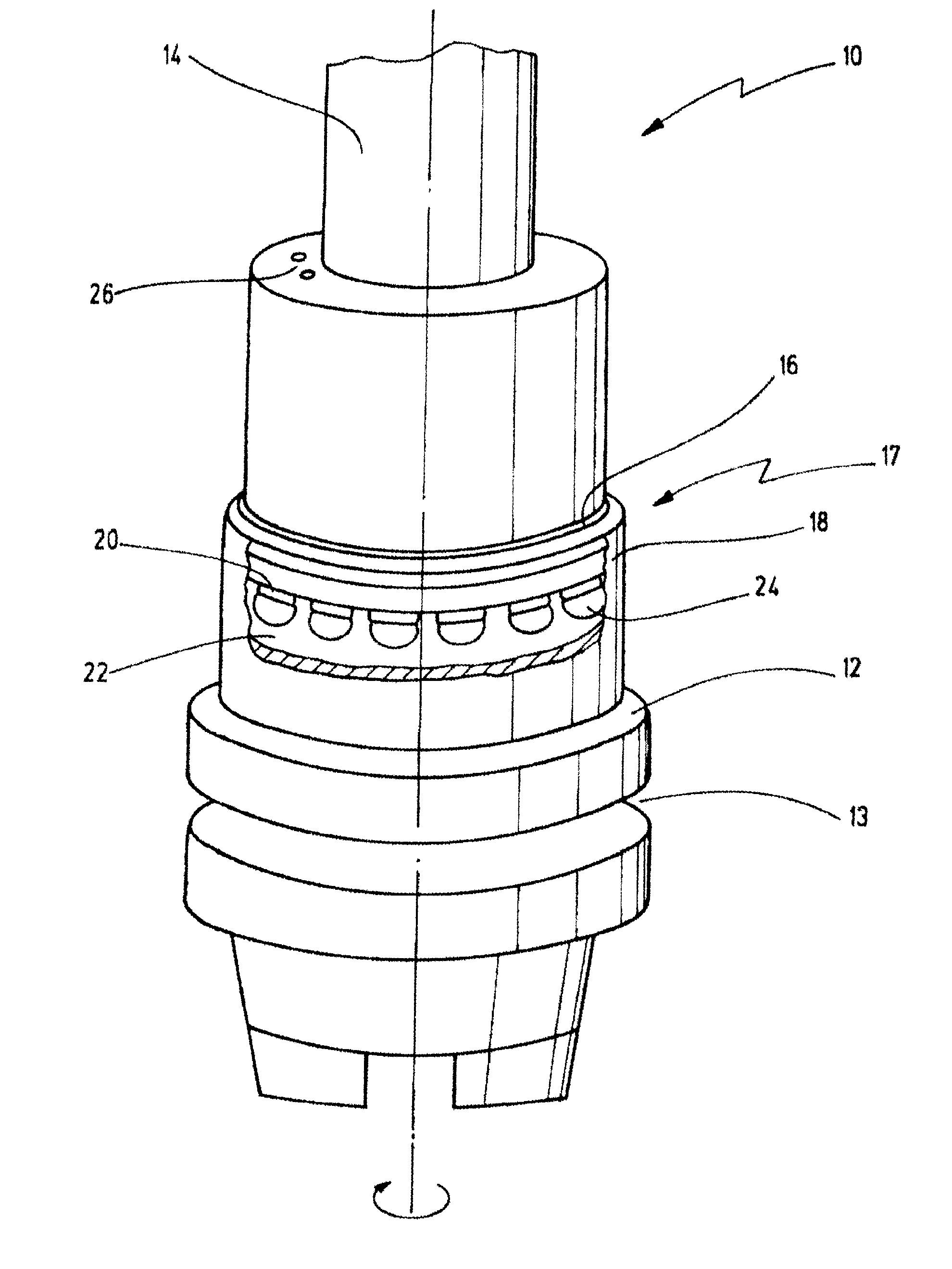
[0072]A simplified embodiment of a tool clamping system according to the invention is illustrated prospectively in FIG. 1 and is designated on the whole by numeral 10.

[0073]The tool clamping system 10 has a tool holder 12 in the form of an HSK, which can be driven in rotation by a tool spindle, for example of a lathe or miller. The tool holder 12 can be formed for example as a shrink chuck or also as a mechanically clampable chuck.

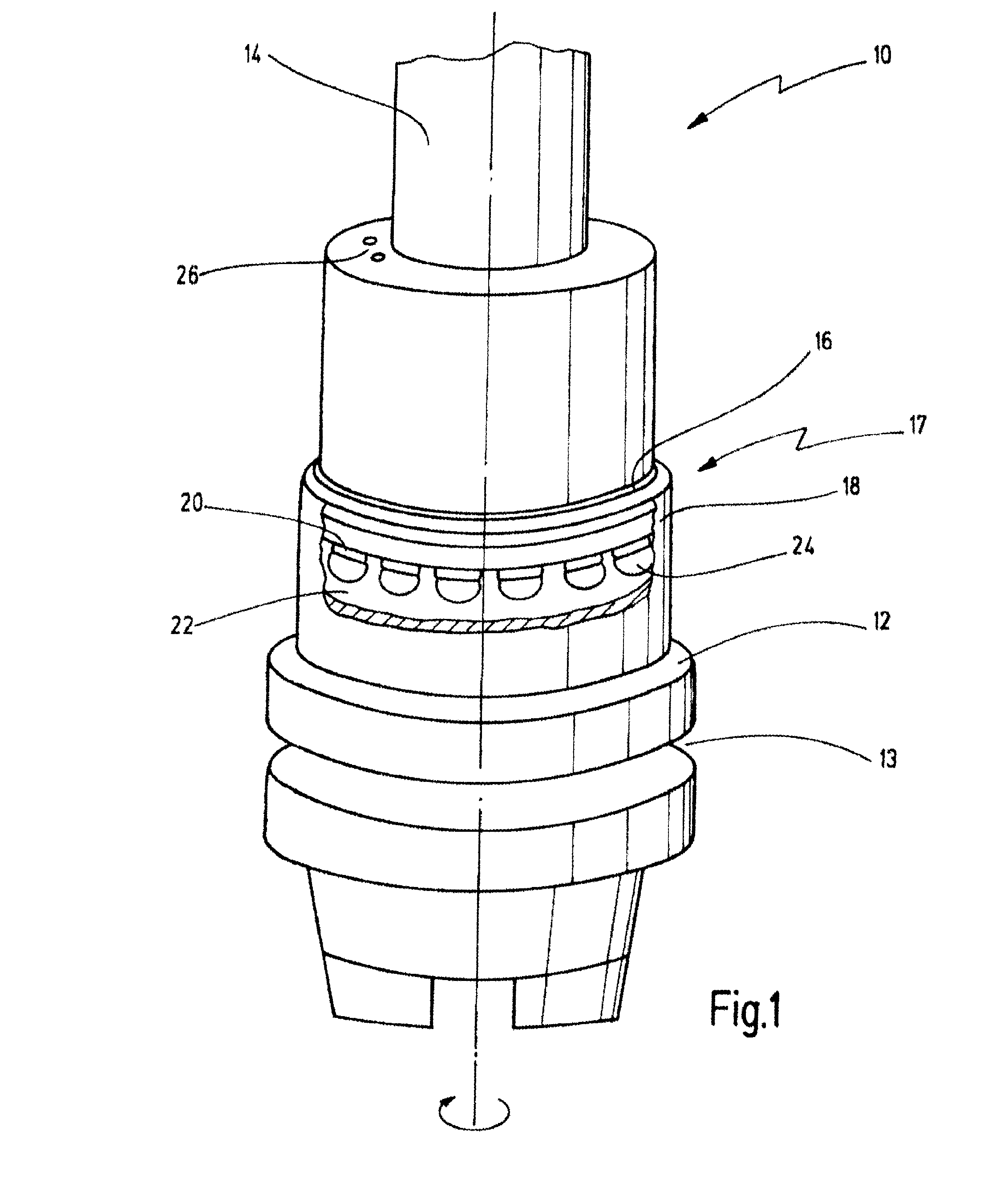
[0074]A voltage generator designated on the whole by 17 is received above a changeover receptacle 13 on the side facing toward the tool 14. In the illustrated case the voltage generator 17 has an inner part or stator part 22 received on the tool holder 12, on which inner part or stator part induction windings 24 are provided. The stator part 22 cooperates with an outer part in the form of a rotor 18 mounted on said stator part by means of a rolling bearing 16, there being permanent magnets 20 provided on the rotor.

[0075]The rotor 18 with the permanent magn...


PUM

PropertyMeasurementUnit
electrical energyaaaaaaaaaa
inertial energyaaaaaaaaaa
inertial massaaaaaaaaaa

Abstract

Disclosed is a tool system including a drive for driving a tool holder including an electromagnetic generator for generating electrical energy from inertial energy of the tool holder. The tool holder may be driven in rotation, wherein the electromagnetic generator comprises a rotor part, which is rotatably mounted on the tool holder, and a stator part on the tool holder cooperating with each other for generating a voltage by electromagnetic induction. Alternatively, an axially movable inertial mass can be used for utilization of an oscillating linear movement.

Description

CROSS-REFERENCES TO RELATED APPLICATIONS[0001]This application is a continuation of international patent application PCT / EP2014 / 057874, filed on Apr. 17, 2014 designating the U.S., which international patent application has been published in German language and claims priority from German patent application 10 2013 105 831.0, filed on Jun. 6, 2013. The entire contents of these applications are incorporated herein by reference.BACKGROUND OF THE INVENTION[0002]The invention relates to a tool clamping system having a mechanically drivable tool holder for clamping a tool.[0003]Tool clamping systems of this type have been known for decades and are used in many ways when machining workpieces.[0004]For some years, it has been required in some machining centers with rotating tools, in addition to the conventional cutting tools, to also provide for measurement-based applications or monitoring operations of the tool. These are generally applications in which a measurement system, usually base...

Claims


Application Information

Patent Timeline
Patent Type & Authority Applications(United States)
IPC IPC(8): B23Q5/04H02K35/00B24B33/10B23B31/02B23Q1/00
CPCB23Q5/043B23B31/02B23Q1/0009B23B2270/022H02K35/00B23B2260/10B23B2260/128B24B33/105B23B31/1179B24B33/08B24B33/10Y10T279/21
Inventor FRONIUS, JUERGENBADER, RUDOLFZIERER, ULRICH
Owner OTTO BILZ WERKZEUGFAB
Why Eureka
Try Eureka