Explosive composition manufacturing and delivery platform, and blasting method
a technology of explosive composition and manufacturing platform, which is applied in the direction of emulsification, explosives, transportation and packaging, etc., can solve the problems of reducing the energy-density of the resultant explosive material, and achieve the effect of easy variation and improved blasting performan
- Summary
- Abstract
- Description
- Claims
- Application Information
AI Technical Summary
Benefits of technology
Problems solved by technology
Method used
Image
Examples
specific embodiment 1
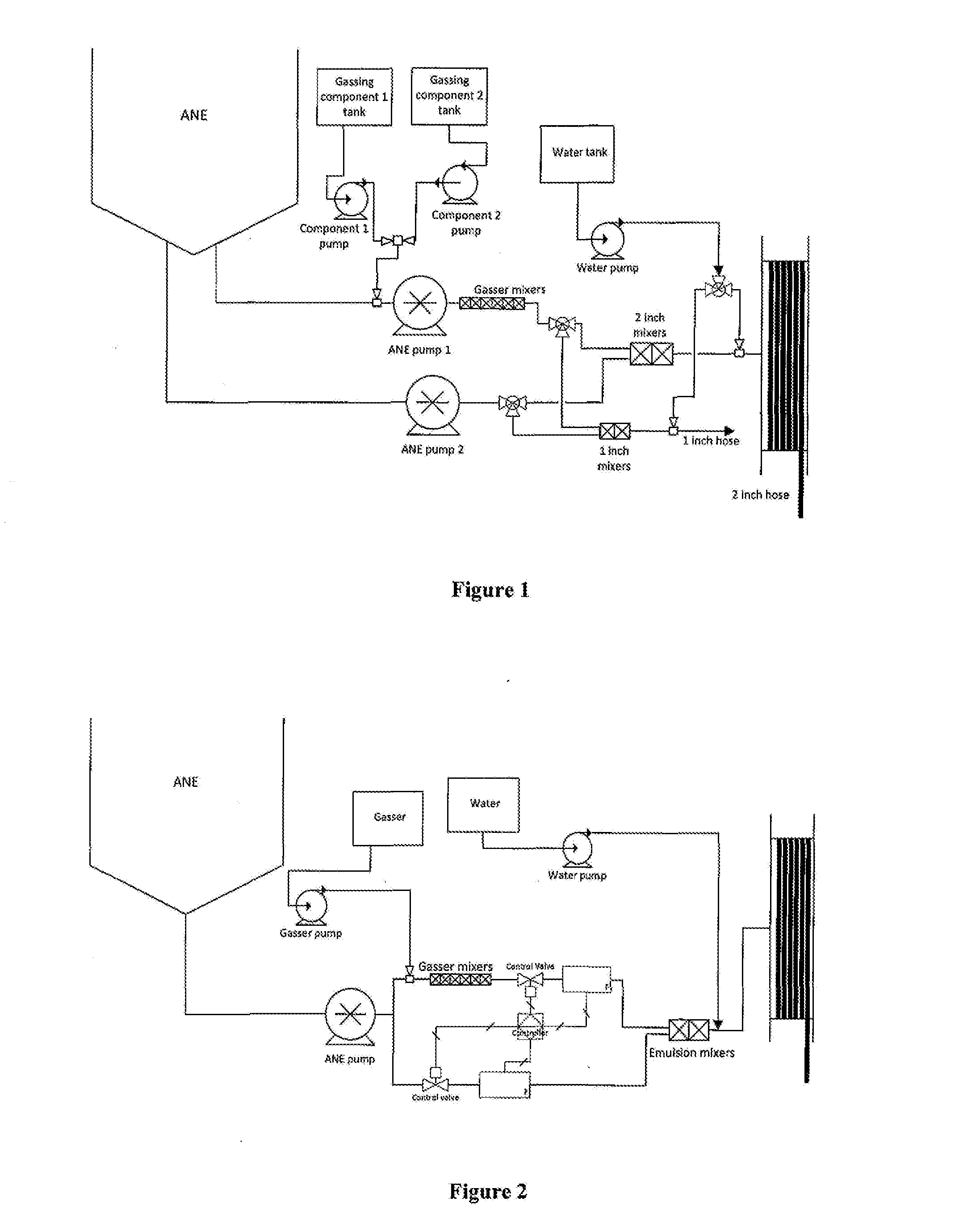
[0078]This specific embodiment is illustrated within FIG. 1 and relies on suitable blending of individual streams of liquid energetic material that have different void concentrations in order to produce an explosive composition having the desired internal structure. A single hopper (tank / reservoir) is used for supplying liquid energetic material, in this case an ammonium nitrate emulsion (ANE). The hopper has two outlet lines with each having an associated pump (for example, progressive cavity pumps) for generating independent flow streams of ANE. The use of two pumps is advantageous as this enables simple process control by varying the pumping rates / ratios. This may also be required when using a hopper or tank that is internally partitioned to accommodate different formulations of liquid energetic material.
[0079]Into one of the streams of liquid energetic material is delivered a chemical gassing solution before that stream is combined with the other stream of unsensitized liquid en...
specific embodiment 2
[0083]This specific embodiment is illustrated in FIG. 2 and also relies on suitable blending of individual streams of liquid energetic material. A single outlet line is used to deliver liquid energetic material from a hopper to a single pump.
[0084]A flow splitting device downstream of the pump can be used to produce two independent flow streams of liquid energetic material. One of the streams produced by flow splitting is processed by delivering into it a chemical gassing solution. Thereafter this stream is blended with the other stream of unsensitized liquid energetic material, previously produced by flow splitting, to achieve the desired (precursor) structure with respect to distribution of (droplets of) chemical gassing solution. Flowmeters on each of the lines, through which the streams flow, may be connected to a control system that drives one or more proportioning valves to control the flow rate of each stream to the mixer.
[0085]As a generally applicable feature, the proportio...
specific embodiment 3
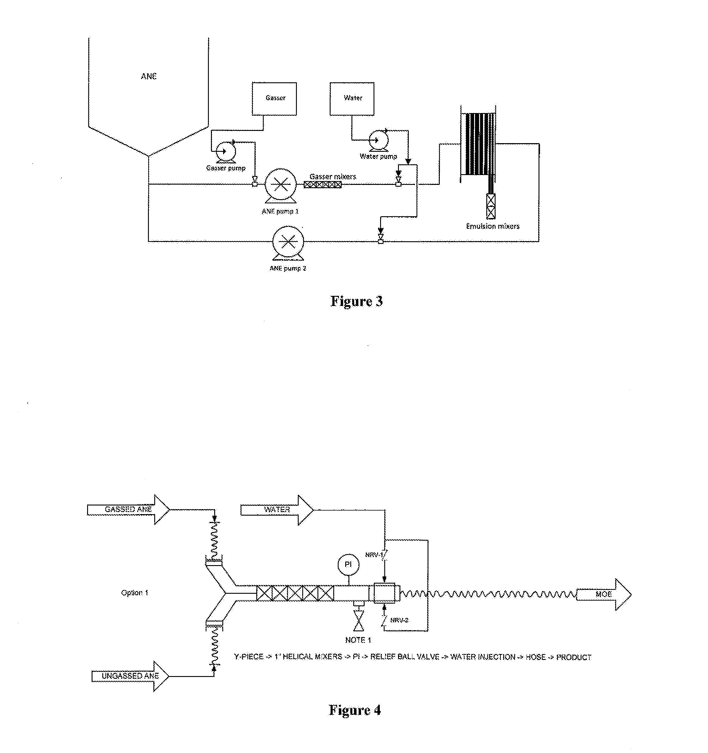
[0088]This specific embodiment is illustrated in FIG. 3 and again relies on suitable blending of individual streams of liquid energetic material that have different void distributions in order to produce an explosive composition having the desired internal structure. However, according to this embodiment, mixing of the streams takes place in the blasthole itself. In this case, each liquid energetic material stream is delivered to a blasthole by means of a hose reel, which can lower or retract two hoses containing the void sensitized (gassed) and non-sensitized (ungassed) emulsion simultaneously. The hoses are connected to a blending head / mixer, which combines the two streams to produce the desired product structure. The arrangement shown in FIG. 3 uses two pumps to provide parallel flow streams of liquid energetic materials, one of which has been dosed with chemical gassing solution. However, the same result may be achieved using a single pump and a flow splitting device as is shown...
PUM
| Property | Measurement | Unit |
|---|---|---|
| volume | aaaaa | aaaaa |
| diameter | aaaaa | aaaaa |
| diameter | aaaaa | aaaaa |
Abstract
Description
Claims
Application Information
 - R&D
- Intellectual Property
- Life Sciences
- Materials
- Tech Scout
- Unparalleled Data Quality
- Higher Quality Content
- 60% Fewer Hallucinations
Browse by: Latest US Patents, China's latest patents, Technical Efficacy Thesaurus, Application Domain, Technology Topic, Popular Technical Reports.
© 2025 PatSnap. All rights reserved.Legal|Privacy policy|Modern Slavery Act Transparency Statement|Sitemap|About US| Contact US: help@patsnap.com


