Anti-wind/Anti-wrapping assembly for trimmers

a technology of anti-wind and anti-wrapping, which is applied in the direction of metal working apparatus, agriculture tools and machines, agriculture, etc., can solve the problems of destroying the system, increasing undesirable and destructive forces, and increasing vibratory forces for operators trying to control the system, etc., to achieve the effect of easy removal

Active Publication Date: 2016-06-02
AERO FLEX TECH
View PDF1 Cites 10 Cited by
  • Summary
  • Abstract
  • Description
  • Claims
  • Application Information

AI Technical Summary

Benefits of technology

[0012]It has been discovered that winding and wrapping can be substantially mitigated by shielding the gaps that pinch the debris and by isolating the sources of rotation that create the winding. The device of the preferred embodiments utilizes a roller, ball or sleeve bearing or the like that separates or isolates the rotating head from a strand or bundle of accumulated debris. The outer race or outer surface of the bearing is free to rotate, and power to the strand is thus disconnected, therefore enabling the strand of vegetation or debris to remain in a more static condition. Even if some winding were to occur, the winding is prevented from being wound tightly enabling easy removal. A shield associated with the bearing further serves to cover pinching gaps between the bearing and the trimmer head as well as between the bearing and adjacent trimmer components.

Problems solved by technology

One of the most irritating experiences when cutting into higher or taller vegetation with a common flexible line trimmer or brush cutter is the wrapping of long strands of vegetation around the axis of rotation of the rotating head.
Additionally, it is not uncommon to run into invisible monofilament fishing line, often left along lake banks and streams that rapidly and very effectively snarls a trimmer head into a stalled rotation.
During the binding process, unless the operator fails to shut down the rotation by releasing the trigger, heat builds up on the rotating or even the stationary parts to cause melting and structural damage to the components, thus often destroying the system.
The degree of bind can vary, but there will more likely be heavy vibration forces due to the imbalance of the wrapped mass to create further trimmer damage.
Certainly, vibratory forces become risky to the operator who is trying to control the system which is now way out of balance.
When combining the problematic imbalance with heat accumulation, it further results in more undesirable and destructive forces as well as melting damage to plastic or non-metallic components.
Most times, the wrappings are so tightly compressed they cannot be removed by hand, nor can the snarl be removed even with needle-nose pliers.
Often it may be best to remove the bound debris from the trimmer with a full disassembly of the head components from the trimmer This is a common nuisance and severe weakness of the trimmer or brush cutter.
While this hand-supported trimmer procedure may be helpful, it is counter to the purpose of a trimmer machine (especially with flexible line blade cutters) that may be ground supported, or more intended to cut lengthy or tall vegetation close to the ground.
Therefore, while nuisance winding is a severe problem when it occurs above the head, there is an added need to prevent or reduce winding when using a ground supported trimmer glider system that utilizes a lower end ‘free-wheeling’ disc to be less vulnerable to the problems of accumulated windings that would likely occur above the head, or below the head (between the glider and the head).
It is also more susceptible to winding and wrapping as it promotes resting the trimmer on the ground to effectively ‘rotary mow’ with a flexible series of line blades.
Therefore, the new method becomes even more vulnerable for debris to then drop down directly onto the rotating head and glider mechanisms to then wrap and bind at either the location above the head or below the head between the head and the glider.
This volume is subject to the accumulation of dropping strands making it even more vulnerable to accumulate the undesirable debris.

Method used


Image

  • Anti-wind/Anti-wrapping assembly for trimmers
  • Anti-wind/Anti-wrapping assembly for trimmers
  • Anti-wind/Anti-wrapping assembly for trimmers

Examples


Embodiment Construction

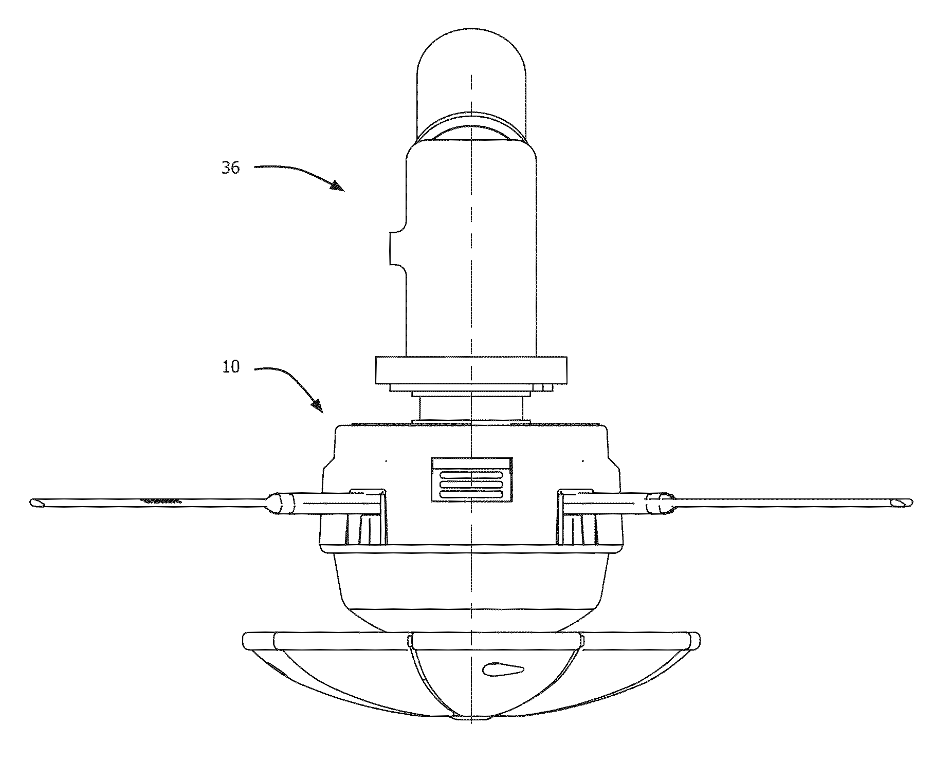
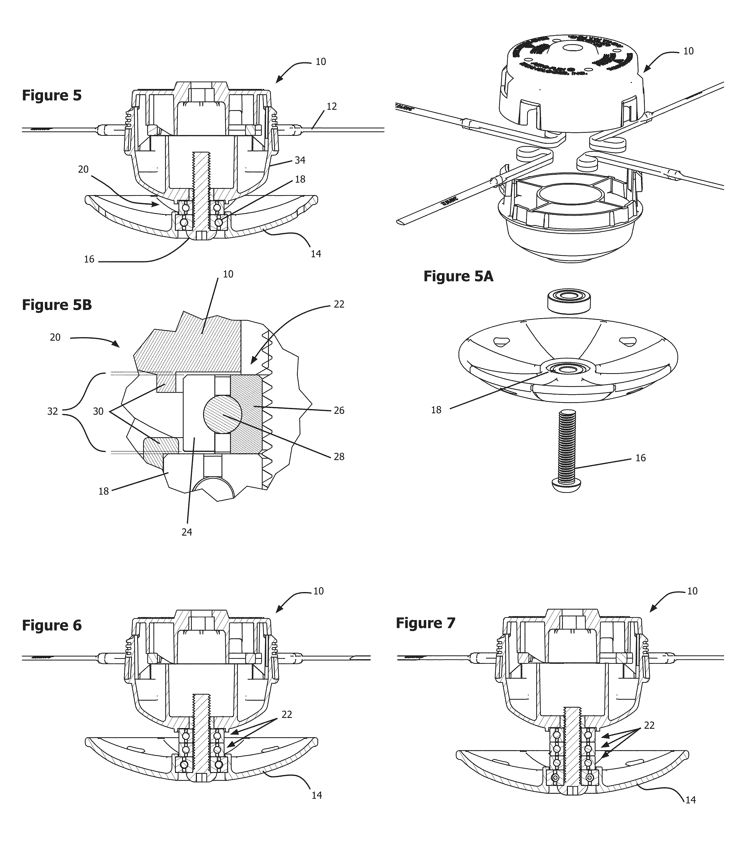
[0026]With reference to FIGS. 5-7, a first exemplary application of the anti-winding assembly will be described in conjunction with a trimmer that incorporates a glider disk such as the glider disk described in the noted co-pending U.S. patent application. A trimmer head 10 is typically secured to a rotatable arbor (not shown in FIG. 5) and supports one or more cutting lines 12. The cutting lines 12 shown in the figures are exemplary molded lines with aerodynamic cross-sections available from Aero-Flex Technologies of Rock Hill, S.C. The cutting lines may also be common monofilament cutting line.

[0027]The glider disk 14 is attached to the trimmer head 10 via a bolt 16 or the like through a glider bearing 18. The anti-winding assembly 20 is positioned in the gap between the glider disk 14 and the trimmer head 10.

[0028]The anti-winding assembly 20 includes a bearing 22 positionable between the trimmer head 10 and the glider disk 14. The bearing includes a freely rotating outer race 24...


PUM


Abstract

An anti-winding assembly reduces or prevents debris from winding on a trimmer and/or makes them easier to remove. The trimmer includes a trimmer head mounted to a rotatable arbor and supporting one or more cutting lines. The anti-winding assembly includes a bearing positionable between the trimmer head and an adjacent trimmer component. The bearing includes a freely rotating outer race. A shield positioned radially outward of the bearing adjacent the outer race shields gaps between the bearing and the trimmer head and between the bearing and the adjacent trimmer component. The anti-winding assembly prevents trimmed debris from being wound up near the trimmer head.

Description

CROSS-REFERENCES TO RELATED APPLICATIONS[0001]This application claims the benefit of U.S. Provisional Patent Application No. 62 / 085,983, filed Dec. 1, 2014, the entire content of which is herein incorporated by reference.STATEMENT REGARDING FEDERALLY SPONSORED RESEARCH OR DEVELOPMENT[0002](NOT APPLICABLE)BACKGROUND OF THE INVENTION[0003]The invention relates to flexible line trimmers and brush cutters and, more particularly, to an anti-wind / wrapping assembly that prevents trimmed debris from winding on a trimmer[0004]One of the most irritating experiences when cutting into higher or taller vegetation with a common flexible line trimmer or brush cutter is the wrapping of long strands of vegetation around the axis of rotation of the rotating head. It also applies to vines, or previously cut vegetation lying on the ground. Additionally, it is not uncommon to run into invisible monofilament fishing line, often left along lake banks and streams that rapidly and very effectively snarls a ...

Claims


Application Information

Patent Timeline
Patent Type & Authority Applications(United States)
IPC IPC(8): A01D34/416
CPCA01D34/4165
Inventor MORABIT, VINCENT D.
Owner AERO FLEX TECH
Why Eureka
Try Eureka