
A Liquid Mixing Collector and a Method for its Use

a technology of liquid mixing collectors and collectors, which is applied in the direction of lighting and heating apparatus, heating types, separation processes, etc., can solve the problems of extensive welding, and achieve the effects of convenient measurement, improved mixing quality, and simple and low cost methods

Active Publication Date: 2016-06-02
SULZER MANAGEMENT AG
View PDF4 Cites 3 Cited by
  • Summary
  • Abstract
  • Description
  • Claims
  • Application Information

AI Technical Summary

Benefits of technology

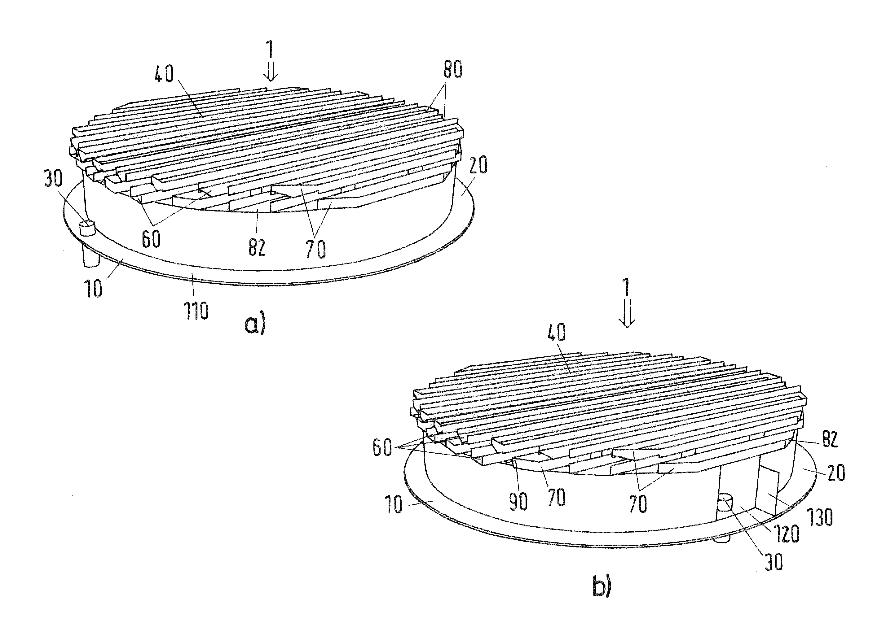
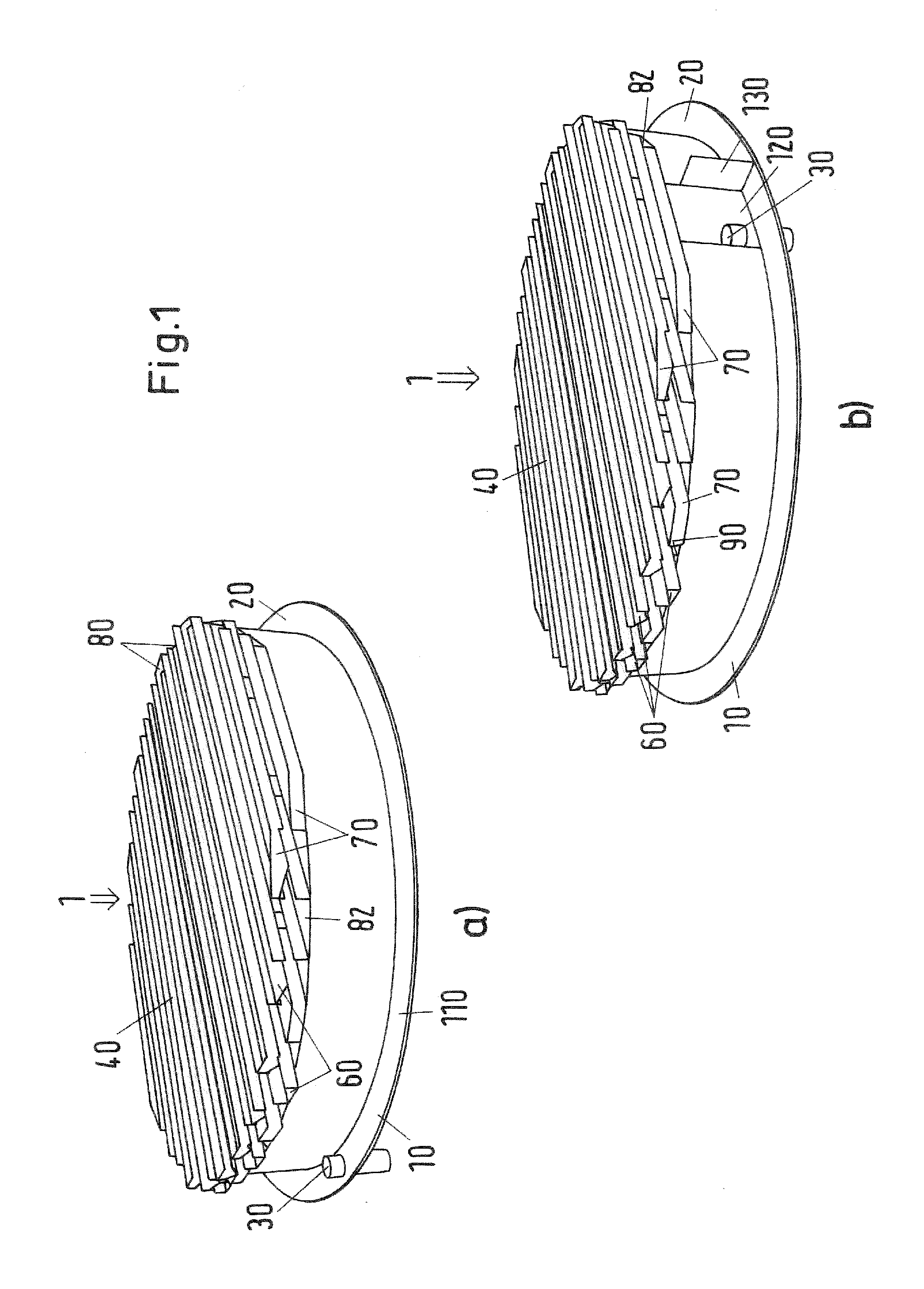
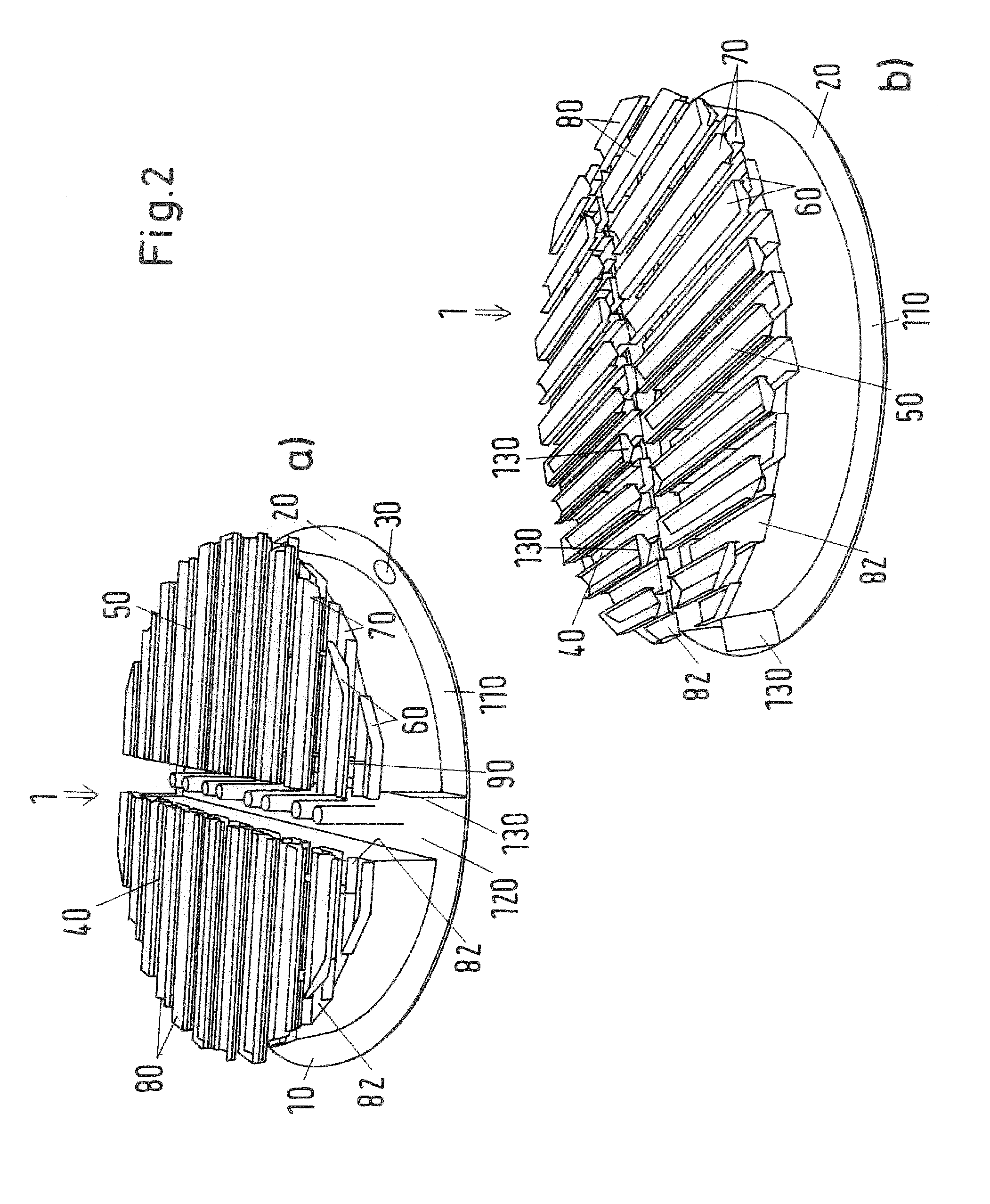
The invention provides a new type of liquid mixing collector that is simpler and less expensive to create than conventional chimney trays. This is because the collector uses a system of liquid collection channels and associated guide plates, mounting plates, and supporting plates or walls, which can be easily fixed without requiring extensive welding. In addition, the invention includes two liquid collection regions that collect the same amount of liquid by adjusting the size and arrangement of the regions and channels. This design ensures a more even mixing of liquids.

Problems solved by technology

This lack of requiring extensive welding is a result of the use of a system of liquid collection channels and underlying associated guide plates and / or mounting plates and / or supporting plates and / or support grids and / or supporting walls on which the channels are mounted.

Method used


Image

  • A Liquid Mixing Collector and a Method for its Use
  • A Liquid Mixing Collector and a Method for its Use
  • A Liquid Mixing Collector and a Method for its Use

Examples


Embodiment Construction

[0056]Definitions

[0057]As used in the specification and claims of this application, the following definitions, should be applied:

[0058]“a”, “an”, and “the” as an antecedent may refer to either the singular or plural unless the context indicates otherwise.

[0059]The term “preferentially flows” as in “liquid when present in said first set of liquid collection channels preferentially flows through the drain openings of the first set of liquid collection channels into said first sump zone” means that this flow pattern is preferential. In one embodiment of the invention, the indicated flow is primarily in the preferential manner (majority of the flow volume). In another embodiment, the flow is substantially all in the preferential manner (i.e. more than 90% by volume), and in another embodiment all of the flow is in the preferential manner.

[0060]The term “preferentially directing” as in “preferentially directing a first quantity of liquid from said first set of liquid collection channels ...


PUM

PropertyMeasurementUnit
heightaaaaaaaaaa
diameteraaaaaaaaaa
massaaaaaaaaaa

Abstract

A liquid mixing collector 1 is disclosed which comprises a first and a second sump zone, 10, 20, a first and optionally a second liquid collection region, 40, 50, a first and a second interspersed set, 60, 70, of spaced apart liquid collection channels 80 positioned in a first liquid collection region 40; said first set 60 being associated with said first sump zone 10; said second set 70 being associated with said second sump zone 20; wherein adjacent liquid collection channels 80 of the first and second sets, 60, 70, are vertically displaced from each other in one of at least two to four parallel horizontal planes 100. The present invention also relates to a column comprising said collector 1, the use of said collector 1 in a mass transfer or heat exchange column, and a method of collecting and mixing descending liquid in a column.

Description

BACKGROUND OF THE INVENTION[0001]The present invention relates to a liquid mixing collector for capturing and mixing liquid descending from an overlying zone in a mass transfer or heat exchange column. The present invention also relates to a mass transfer or heat exchange column comprising said collector, use of said collector in a mass transfer or heat exchange column, and a method of collecting and mixing descending liquid in a mass transfer or heat exchange column.[0002]Mass transfer columns, including heat exchange columns, typically include a shell and a plurality of zones within the shell in which packing and / or trays are used to facilitate mass or heat transfer between fluid streams flowing within the column. The fluid streams are normally one or more downwardly flowing liquid streams and one or more ascending vapor streams, although other combinations of fluid streams may be possible. Liquid exiting the bottom of a zone may have different concentrations and compositions at d...

Claims


Application Information

Patent Timeline
Patent Type & Authority Applications(United States)
IPC IPC(8): B01D3/32B01F3/04
CPCB01D3/324B01F3/04468B01F3/04078B01D3/20B01D3/24B01F23/214B01F23/2321
Inventor WEHRLI, MARCBACHMANN, CHRISTIAN G.BRACK, HANS-PETERKEHRER, FLORIAN
Owner SULZER MANAGEMENT AG
Learn More