
Pneumatic Nail Gun Capable of Striking Nails in Automatic Mode

a nail gun and pneumatic technology, applied in the field of pneumatic nail guns, can solve the problems of inability to afford automatic actuation mode operation, inability to initiate the drive stroke of the nail gun, and the above-described nail gun can only be operated in restriction actuation mode or contact actuation mode, and achieve the effect of simplifying the structur

Inactive Publication Date: 2016-06-02
DE POAN PNEUMATIC
View PDF4 Cites 29 Cited by
  • Summary
  • Abstract
  • Description
  • Claims
  • Application Information

AI Technical Summary

Benefits of technology

The present invention is about a pneumatic nail gun that has a simplified structure and can operate in automatic actuation mode for fast, repeatedly striking nails. The gun has a cylinder with a poppet valve and a piston with a drive blade. A trigger valve regulates the pressurized air in the main chamber to enter the top chamber via a trigger passage, and a shuttle valve regulates the pressurized air to be released to atmosphere via the trigger passage. The gun also has a forward air conduit and a return air conduit to guide the pressurized air and has a simplified structure that can save manufacturing costs. The technical effects of the invention are that it allows for stable operation in automatic actuation mode, simplifies the structure of the nail gun, and reduces manufacturing costs.

Problems solved by technology

When the operational sequence of the nail gun is violated, i.e., the trigger is pulled before depressing the safety bar or the contact head, the trigger's spring cannot be moved to a state that allows the trigger valve to act properly, thereby disabling the function of initiating a drive stroke on the nail gun.
However, in the existing technology, when the safety bar has been depressed, the nail gun or the automatic machine incorporating a nail gun cannot fire multiple strokes by pulling the trigger a single time; namely, the nail gun or the automatic machine of the existing technology is unable to afford an operation of automatic actuation mode.
However, the above-disclosed nail guns can only be operated in restriction actuation mode or contact actuation mode.
They cannot be operated in automatic actuation mode; namely, they cannot achieve the function of conducting repeated strokes by pulling and releasing the trigger a single time.
Besides, due to the complex designs of pneumatic passages or conduits, they may have a problem in the stability of operating the nail guns, especially when they are applied in an operation that requires striking nail fast and repeatedly.

Method used


Image

  • Pneumatic Nail Gun Capable of Striking Nails in Automatic Mode
  • Pneumatic Nail Gun Capable of Striking Nails in Automatic Mode
  • Pneumatic Nail Gun Capable of Striking Nails in Automatic Mode

Examples


Embodiment Construction

[0027]To illustrate the technical contents of the present invention, two embodiments are provided in the following paragraphs.

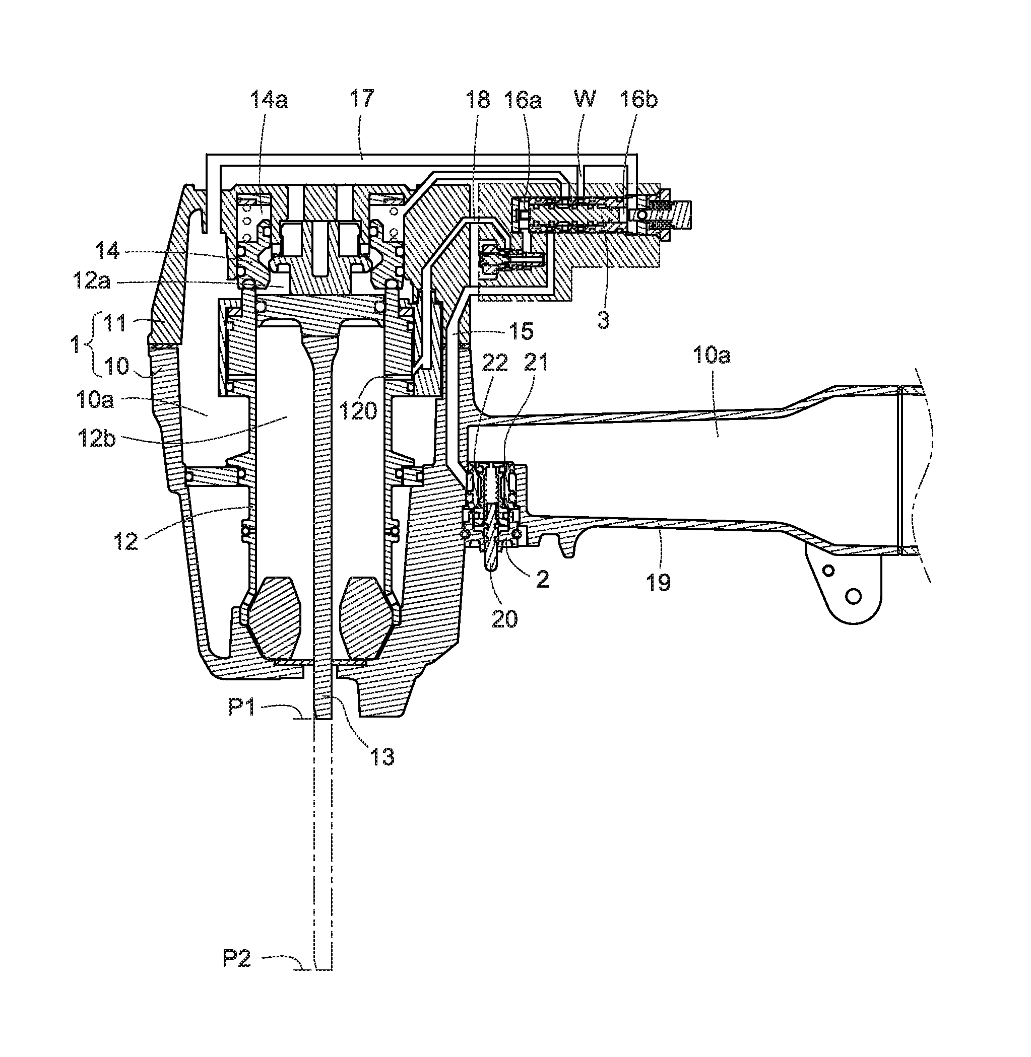
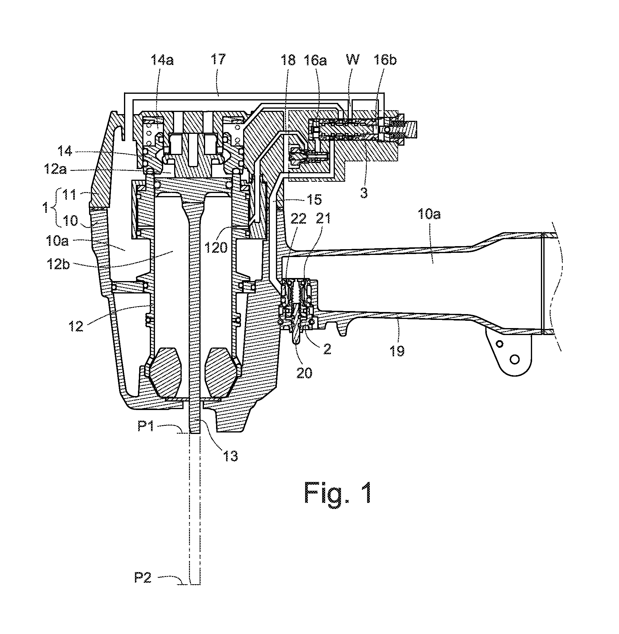
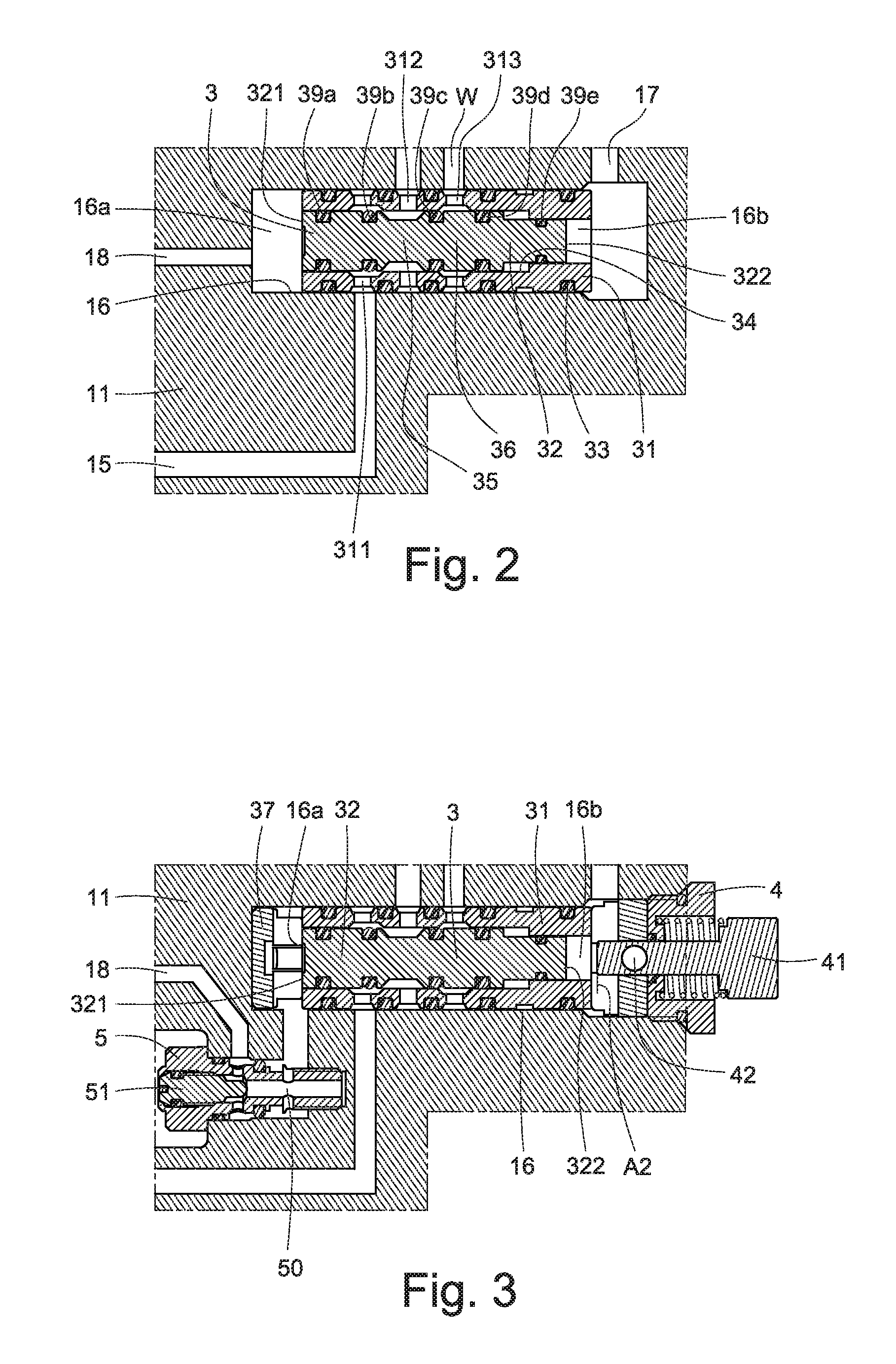
[0028]Referring first to FIGS. 1 through 5, 6a, 6b, 6c, 6d and 6e, a pneumatic nail gun according to a first embodiment of the present invention is shown, which generally comprises a gun body 1, a trigger valve 2, and a shuttle valve 3.

[0029]As shown in FIG. 1, the gun body 1 includes a main housing 10 and a cover 11 on top of the main housing 10. The main housing 10 is provided therein with a cylinder 12. A piston together with a drive blade13 is slidably fitted in the cylinder 12, so that the interior of the cylinder 12 is divided into an upper chamber 12a and a lower chamber 12b, each of which has a variable volume. On top of the piston is provided with a poppet valve 14, which is a discoid element biased by a spring. On top of the poppet valve 14 is defined with a top chamber 14a. Also, the gun body 10 defines therein a main chamber 10a, which is supplied...


PUM


Abstract

A pneumatic nail gun operated in automatic actuation mode includes a gun body, a trigger valve, and a shuttle valve. The gun body defines therein a main chamber and is provided with a forward air conduit and a return air conduit. The forward air conduit provides a path for the pressurized air in the main chamber to force a valve stem of the shuttle valve to conduct a forward movement for a drive stroke. The return air conduit provides a path for the pressurized air in the cylinder to force the valve stem to conduct a return movement after the nail gun has completed the drive stroke. By depressing an actuating bar of the trigger valve a single time, the valve stem can be forced to conduct repeated forward and return movements, and thus the nail gun can conduct repeated drive strokes for stably striking a nail.

Description

TECHNICAL FIELD OF THE INVENTION[0001]The present invention relates to a pneumatic nail gun and, more particularly, to a pneumatic nail gun provided with a shuttle valve, which allows the nail gun to be stably operated in automatic actuation mode for striking nails.DESCRIPTION OF THE PRIOR ART[0002]Pneumatic nail guns are a tool that employs pressurized air to move a piston thereof to conduct a drive stroke for striking a nail and a return stroke for preparing a next striking. Generally, the operation of a pneumatic nail gun can be divided into two modes: restriction actuation and contact actuation.[0003]When a pneumatic nail gun is operated in restrictive actuation mode, at first, the user should place a contact head of the nail gun against a workpiece to have a safety bar associated therewith push a spring of the gun's trigger. Next, the trigger of the nail gun can be pulled to initiate a drive stroke for striking a nail into the workpiece. In this mode, when a second drive stroke...

Claims


Application Information

Patent Timeline
Patent Type & Authority Applications(United States)
IPC IPC(8): B25C1/04
CPCB25C1/047B25C1/043
Inventor WU, I-TSUNGMA, HAI-LUNLIAO, ZHEN-LIANG
Owner DE POAN PNEUMATIC
Learn More