Liquid crystal display device
- Summary
- Abstract
- Description
- Claims
- Application Information
AI Technical Summary
Benefits of technology
Problems solved by technology
Method used
Image
Examples
examples
[0210]Although some best modes of the present invention will now be described in detail with reference to Examples, the present invention is not limited to Examples. In compositions which will be described in Examples and Comparative Examples, the term “%” refers to “mass %”.
[0211]In Examples, the following properties were measured.
[0212]Tni: nematic phase-isotropic liquid phase transition temperature (° C.)
[0213]Δn: refractive index anisotropy at 25° C.
[0214]Δ∈: dielectric constant anisotropy at 25° C.
[0215]η: viscosity at 20° C. (mPa·s)
[0216]γ1: rotational viscosity at 25° C. (mPa·s)
[0217]dgap: gap between first and second substrates in cell (μm)
[0218]VHR: voltage holding ratio at 70° C.
(ratio, represented by %, of measured voltage to initial applied voltage, which was obtained as follows: a liquid crystal composition was put into a cell having a thickness of 3.5 μm, and the measurement was carried out under the conditions of applied voltage of 5 V, frame time of 200 ms and pulse ...
examples 1 to 4
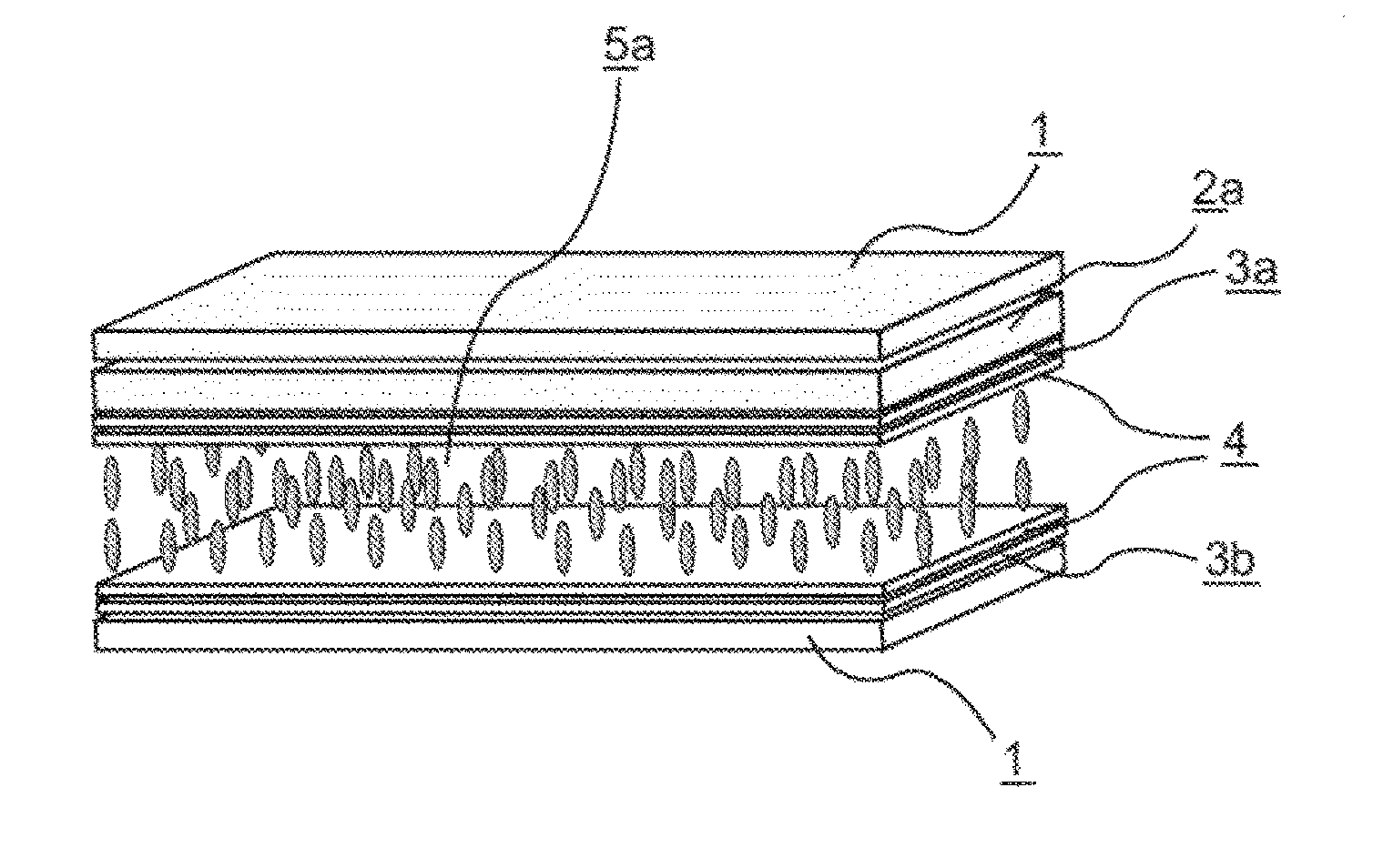
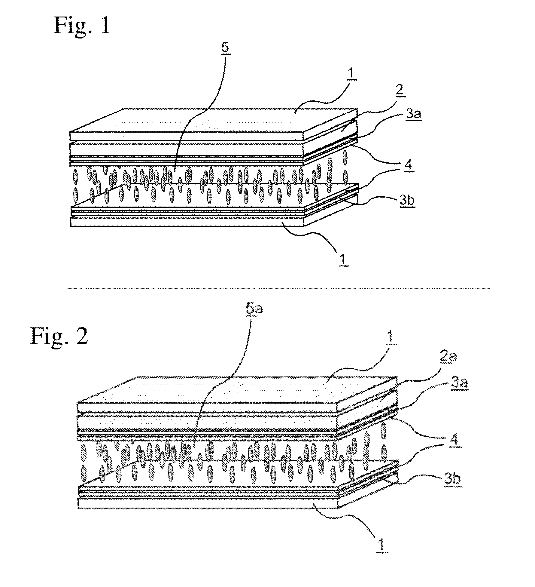
[0268]Electrodes corresponding to first and second substrates were formed, vertical alignment films were formed on the facing surfaces thereof, the alignment films were slightly rubbed to form VA cells, and then a liquid crystal composition 1 shown in Table 9 was placed between the first and second substrates. Then, the color filters 1 to 4 shown in Table 8 were used to produce liquid crystal display devices of Examples 1 to 4 (dgap=3.5 μm and alignment film SE-5300). The VHR and ID of the produced liquid crystal display devices were measured. The screen burn-in of each liquid crystal display device was evaluated. Table 10 shows results of the measurement and evaluation.
TABLE 9Liquid crystal composition 1TNI / ° C.81.0Δn0.103Δε−2.9η / mPa · s20.3γ1 / mPa · s112γ1 / Δn2 × 10−21053-Cy-Cy-224% 3-Cy-Cy-410% 3-Cy-Cy-55%3-Cy-Ph—O12%3-Cy-Ph5—O213% 2-Cy-Ph—Ph5—O29%3-Cy-Ph—Ph5—O29%3-Cy-Cy-Ph5—O35%4-Cy-Cy-Ph5—O26%5-Cy-Cy-Ph5—O25%3-Ph—Ph5—Ph-26%4-Ph—Ph5—Ph-26%
TABLE 10Example 1Example 2Example 3Example...
examples 5 to 12
[0271]As in Example 1, liquid crystal compositions shown in Table 11 were placed, the color filters shown in Table 8 were used to produce liquid crystal display devices of Examples 5 to 12, and the VHR and ID thereof were measured. The screen burn-in of each liquid crystal display device was evaluated. Tables 12 and 13 show results of the measurement and evaluation.
TABLE 11Liquid crystal composition 2TNI / ° C.76.0Δn0.103Δε−2.9η / mPa · s19.8γ1 / mPa · s110γ1 / Δn2 × 10−21033-Cy-Cy-224% 3-Cy-Cy-410% 3-Cy-Ph—O17%3-Cy-Ph5—O214% 2-Cy-Ph—Ph5—O27%3-Cy-Ph—Ph5—O29%3-Cy-Cy-Ph5—O35%4-Cy-Cy-Ph5—O27%5-Cy-Cy-Ph5—O25%3-Ph—Ph5—Ph-26%4-Ph—Ph5—Ph-26%Liquid crystal composition 3TNI / ° C.84.8Δn0.103Δε−2.9η / mPa · s21.4γ1 / mPa · s119γ1 / Δn2 × 10−21123-Cy-Cy-224% 3-Cy-Cy-411% 3-Cy-Ph5—O212% 2-Cy-Ph—Ph5—O25%3-Cy-Ph—Ph5—O26%3-Cy-Cy-Ph5—O38%4-Cy-Cy-Ph5—O28%5-Cy-Cy-Ph5—O28%3-Ph—Ph5—Ph-26%4-Ph—Ph5—Ph-26%5-Ph—Ph-13%3-Cy-Cy-Ph-13%
TABLE 12Example 5Example 6Example 7Example 8LiquidLiquidLiquidLiquidLiquidcrystalcrystalcrys...
PUM
 Abstract
Description
Claims
Application Information
 - R&D
- Intellectual Property
- Life Sciences
- Materials
- Tech Scout
- Unparalleled Data Quality
- Higher Quality Content
- 60% Fewer Hallucinations
Browse by: Latest US Patents, China's latest patents, Technical Efficacy Thesaurus, Application Domain, Technology Topic, Popular Technical Reports.
© 2025 PatSnap. All rights reserved.Legal|Privacy policy|Modern Slavery Act Transparency Statement|Sitemap|About US| Contact US: help@patsnap.com


