
Drive assist system, method, and program

a technology of driver assistance and driver, applied in the direction of navigation instruments, instruments, maps/plans/charts, etc., can solve the problems of user mislead, unavoidable occurrence of position errors,

Active Publication Date: 2016-06-02
AISIN AW CO LTD
View PDF29 Cites 8 Cited by
  • Summary
  • Abstract
  • Description
  • Claims
  • Application Information

AI Technical Summary

Benefits of technology

The patent describes a technology that prevents the destination icon from being passed by in a configuration where it is overlaid on a scene.

Problems solved by technology

In a technology for specifying the current location of a vehicle, however, occurrence of an error in position is unavoidable.
Therefore, in the case where an error has occurred, the arrow pointing to the target scene position may be displayed at a position that is different from the target scene position, in which case the user may be misled.

Method used


Image

  • Drive assist system, method, and program
  • Drive assist system, method, and program
  • Drive assist system, method, and program

Examples


Embodiment Construction

[0013]An embodiment will be described below in the following order:

[0014](1) Configuration of Navigation System

[0015](2) Drive Assist Process

[0016](3) Other Embodiments

(1) Configuration of Navigation System

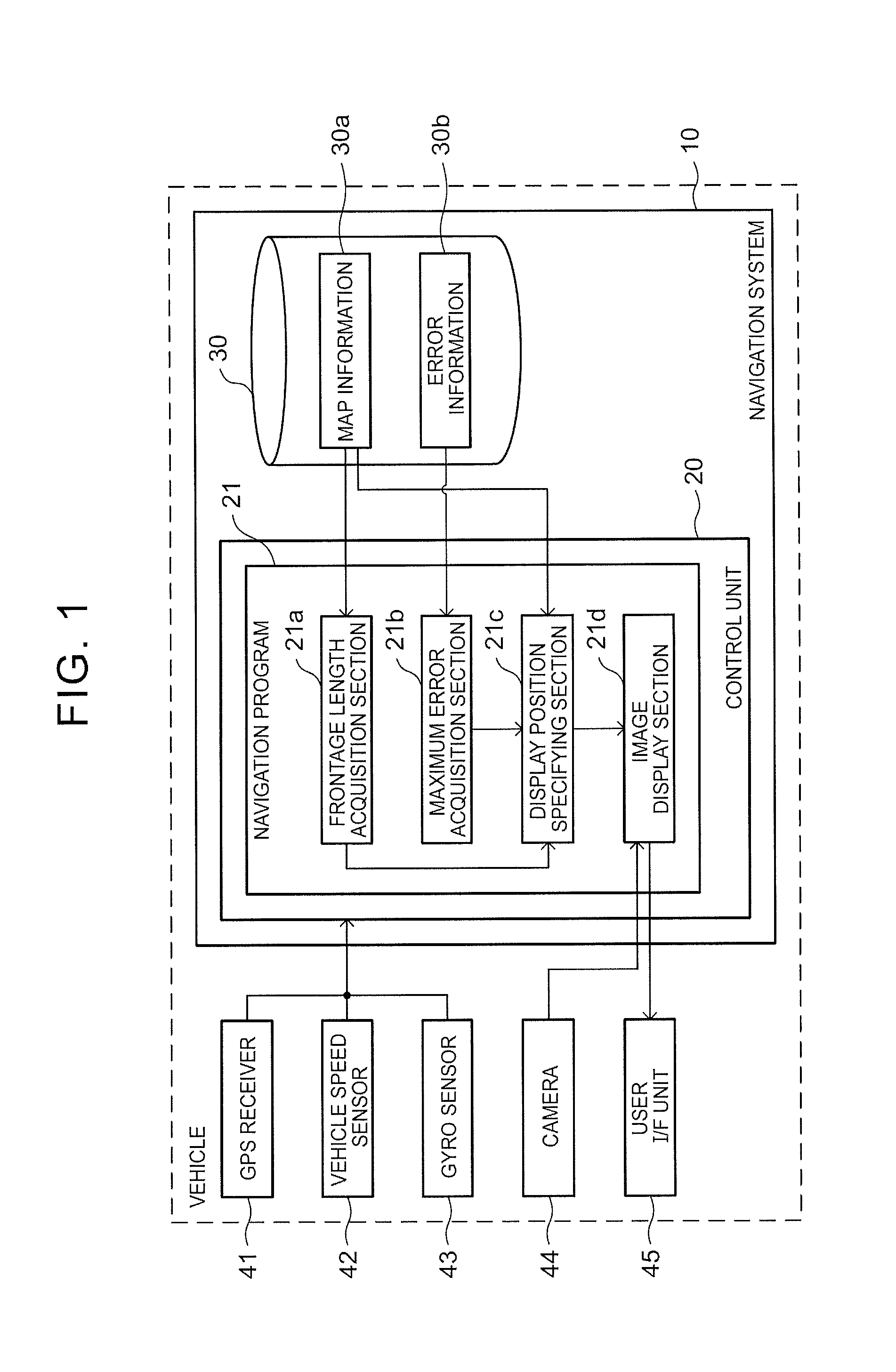
[0017]FIG. 1 is a block diagram illustrating the configuration of a navigation system 10 that includes a drive assist system. The navigation system 10 is provided in a vehicle that serves as a mobile body, and includes a control unit 20 that includes a CPU, a RAM, a ROM, and so forth and a storage medium 30. (As used herein the term “storage medium” does not encompass transitory signals.) The navigation system 10 can execute a program such as a navigation program 21 stored in the storage medium 30 or the ROM using the control unit 20.

[0018]In addition, the vehicle according to the embodiment includes a GPS receiver 41, a vehicle speed sensor 42, a gyro sensor 43, a camera 44, and a user I / F unit 45. The GPS receiver 41 receives radio waves from GPS satellites to output a signal in...


PUM


Abstract

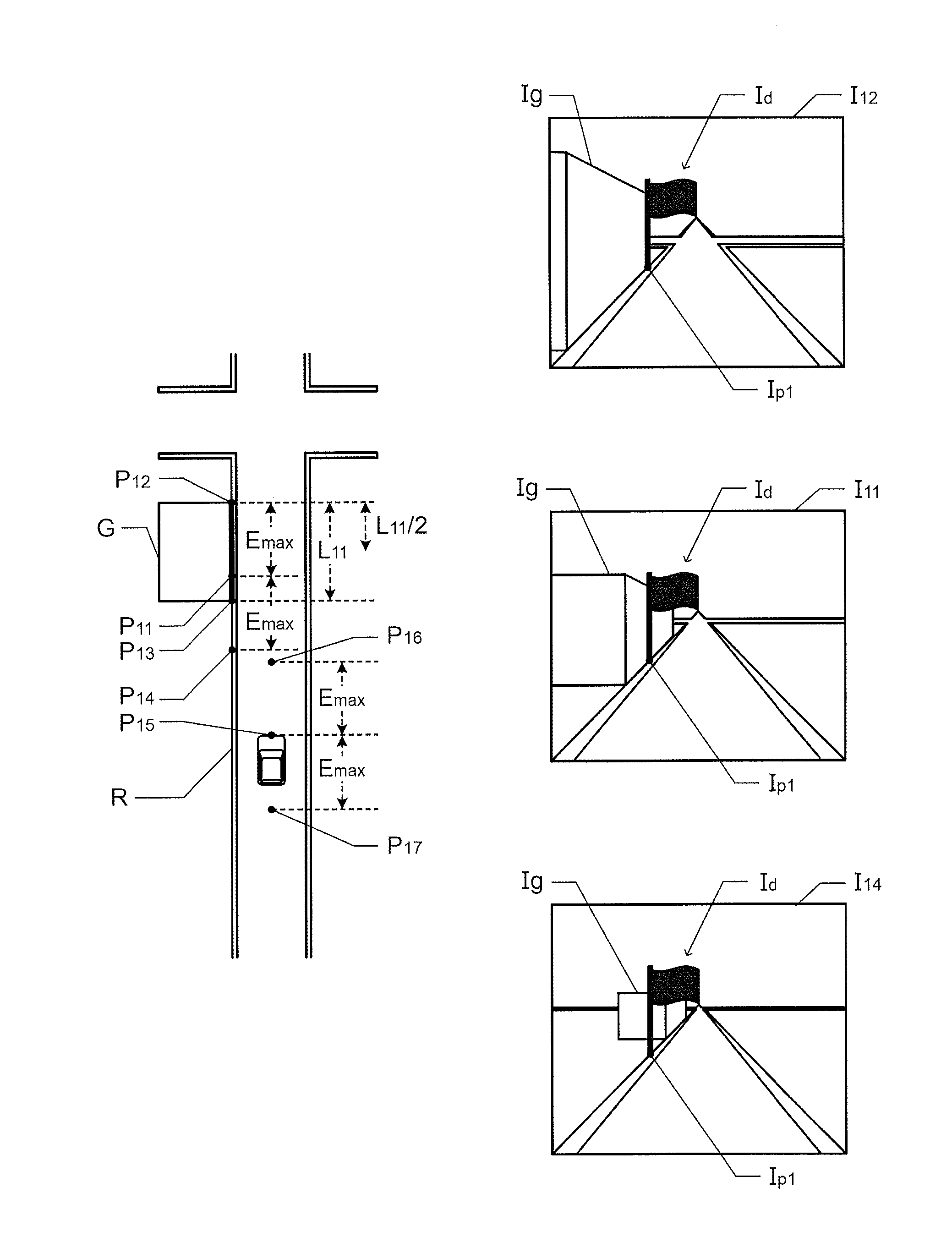
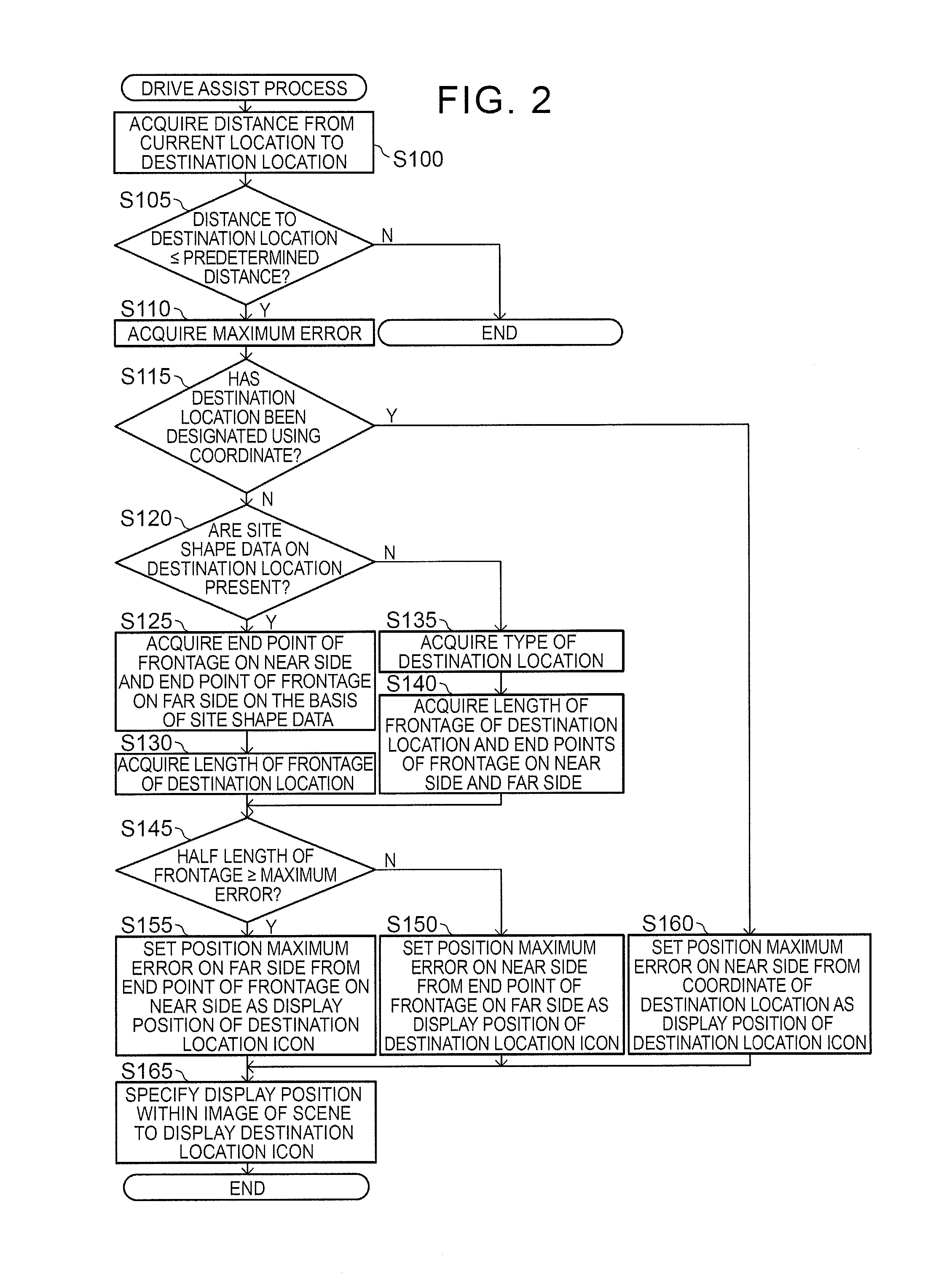
Drive assist systems, methods, and programs display, on a display, an image in which a destination location icon that indicates a destination location is superimposed on a scene in front of a mobile body. The systems, methods, and programs acquire a length of a frontage of the destination location along a road on which the mobile body is present and specify a display position of the destination location icon on the basis of an estimated position of the mobile body such that the display position of the destination location icon is a position within the frontage. The systems, methods, and programs display on the display, an image in which the destination location icon is superimposed on the display position of the destination location icon in the scene in front of the mobile body.

Description

TECHNICAL FIELD[0001]Related technical fields include drive assist systems, methods, and programs.BACKGROUND ART[0002]There has hitherto been known a technology for causing a user to focus on a destination location by superimposing a predetermined icon on a location within a scenic image that illustrates a scene in front of a vehicle in the case where an image of the destination location is included in the scenic image. For example, Japanese Patent Application Publication No. 2011-154041 (JP 2011-154041 A) discloses a technology for combining an image of an arrow that points to a target scene position with an image captured using a camera.SUMMARY[0003]In the related art discussed above, the target scene position within the image captured using the camera is specified on the basis of the current location of the vehicle. Thus, the target scene position within the image depends on the current location of the vehicle. In a technology for specifying the current location of a vehicle, how...

Claims


Application Information

Patent Timeline
Patent Type & Authority Applications(United States)
IPC IPC(8): G01C21/36
CPCG01C21/3626G09B29/007
Inventor SATO, YUJIMORI, TOSHIHIRONAKAO, KOICHI
Owner AISIN AW CO LTD
Learn More