
System and method of conducting particle monitoring using low cost particle sensors

a particle sensor and low-cost technology, applied in the field of detection of particles, can solve the problems of inability to perform calibrations frequently in the field, the calibration process is typically laborious and expensive, and the calibration is usually only done infrequently, so as to reduce the cost of pollution measurement systems and reduce the cost. the effect of cost and accuracy

Active Publication Date: 2016-06-02
TSI INC
View PDF4 Cites 50 Cited by
  • Summary
  • Abstract
  • Description
  • Claims
  • Application Information

AI Technical Summary

Benefits of technology

The invention provides a cost-effective solution for calibrating particle sensors in the field, which helps improve accuracy for low-concentration pollution measurements. This solution involves using optical sensors such as optical particle counters and photometers, which measure the light scattered or attenuated by the particles. To account for the refractive indices and morphology of the aerosol, these sensors can be calibrated against a theoretical scattering model or a reference measurement instrument. The calibration process is typically labor-intensive and expensive, but the invention provides an easy and cost-free way to calibrate these sensors remotely, without the requirement of a reference instrument physically located in the same place as the sensor(s). This makes it more practical to perform calibrations frequently in the field, which can help decrease the cost of pollution measurement systems with a wide geographic coverage.

Problems solved by technology

In practice, however, calibration is usually only done infrequently because the reference instruments are typically only available in the laboratories or at certain fixed locations due to their large size and high cost.
Further, the calibration process is typically labor intensive and expensive so it is not practical to perform calibrations frequently in the field.

Method used


Image

  • System and method of conducting particle monitoring using low cost particle sensors
  • System and method of conducting particle monitoring using low cost particle sensors
  • System and method of conducting particle monitoring using low cost particle sensors

Examples


Embodiment Construction

[0026]Following are more detailed descriptions of various related concepts related to, and embodiments of, methods and apparatus according to the present disclosure. It should be appreciated that various aspects of the subject matter introduced above and discussed in greater detail below may be implemented in any of numerous ways, as the subject matter is not limited to any particular manner of implementation. Examples of specific implementations and applications are provided primarily for illustrative purposes.

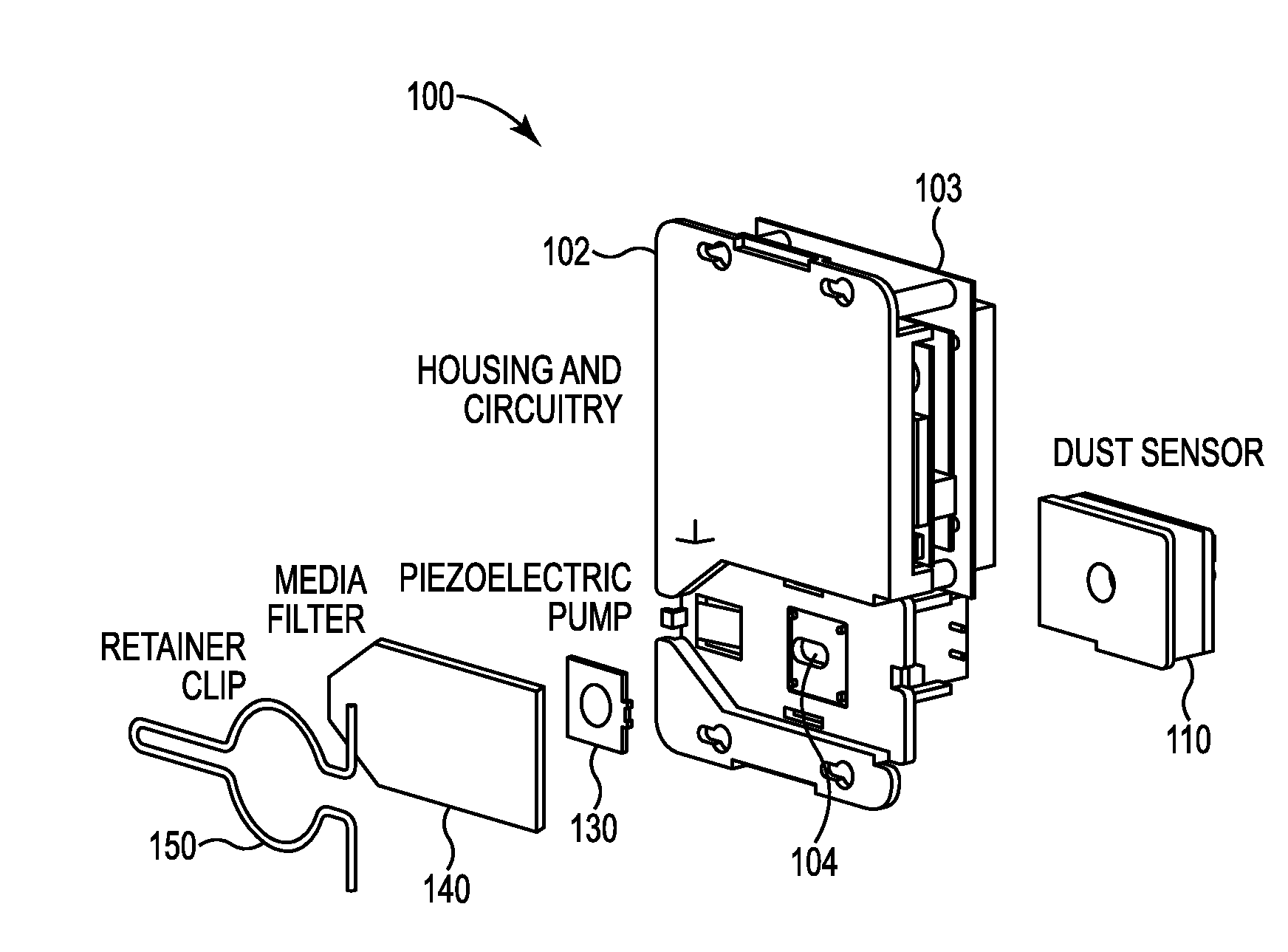
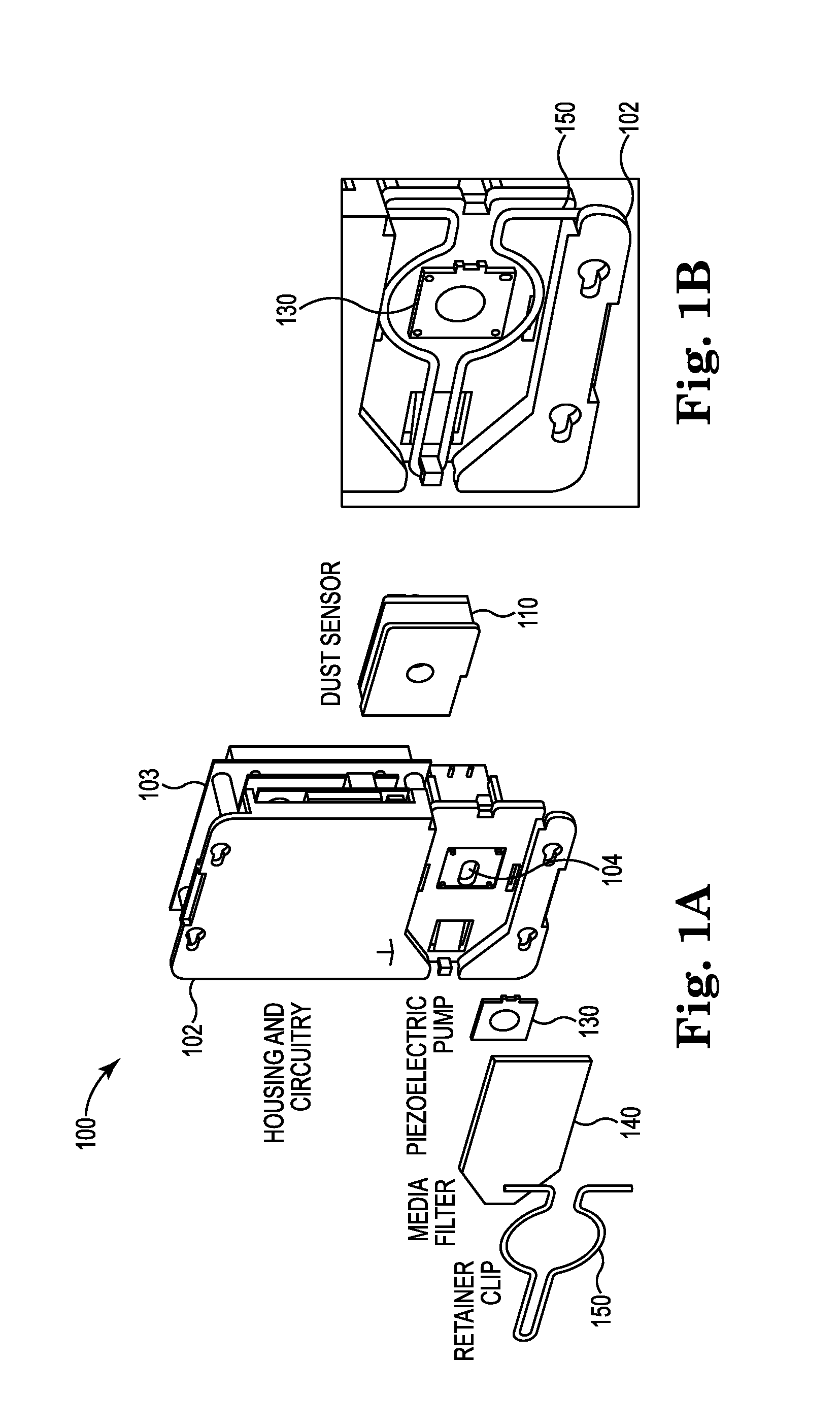
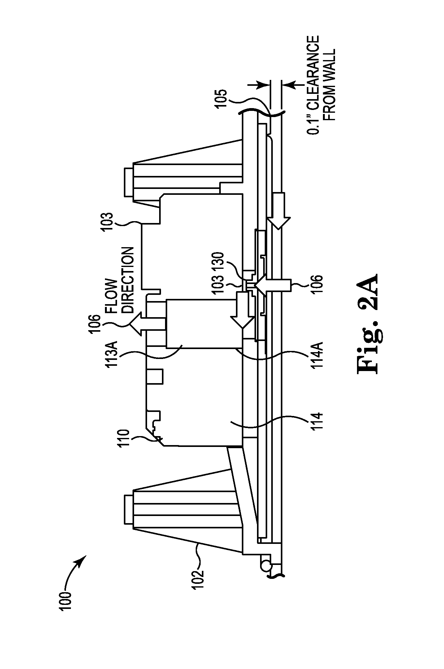
[0027]In one example embodiment, there is disclosed an inexpensive and very compact device that addresses the requirement of frequent zero calibration of a low-cost sensor. The low-cost particle sensor incorporates a unique and compact piezoelectric microblower and filter material to periodically pass filtered air through a photometric sensor to provide more accurate low-concentration measurements. In this example embodiment, the piezoelectric microblower has an advantage ove...


PUM


Abstract

There is disclosed a field calibratable particle sensor solution in a low-cost, very compact form factor. This makes a low-cost sensor more accurate for low-concentration pollution measurements and decreases the cost of pollution measurement systems having a wide geographic coverage. In a related embodiment, the invention illustrates a method and system to remotely and automatically calibrate one or more of the low cost sensors disclosed herein as well as other commercially available sensors (such as optical particle counters, photometers etc.) against a reference instrument (such as a beta attenuation monitor) which may or may not be physically located in the same place as the individual sensors. The method may require minimum (or no) user interaction and the calibration period is adjustable periodically.

Description

CLAIM OF PRIORITY[0001]This application claims priority to and the benefit of U.S. Provisional Patent Application No. 62 / 086,414, filed Dec. 2, 2014 and titled “SYSTEM AND METHOD OF CONDUCTING PARTICLE MONITORING USING LOW COST PARTICLE SENSORS” which application is incorporated herein by reference in its entirety.FIELD AND BACKGROUND OF THE INVENTION[0002]The invention generally relates to the detection of particles, and more specifically to the measurement of dust particle concentrations and size distributions.[0003]When inhaled, aerosol particles can deposit on the respiratory track and cause adverse health effects. Hence, industry and government have recognized the importance of measuring and monitoring aerosol concentrations in the environment or workplace so that proper measures can be taken to reduce potential health risks. Pertinent monitoring applications include but are not limited to commercial building or home air quality monitoring, industrial / occupational hygiene surve...

Claims


Application Information

Patent Timeline
IPC IPC(8): G01N15/06G01N1/22
CPCG01N15/0618G01N2001/2223G01N1/2205G01N15/06G01N1/2273G01N15/075
Inventor HAN, HEE-SIEWFARNSWORTH, JAMES E.CALDOW, ROBERT
Owner TSI INC
Learn More