Circuit connectivity and conveyance of power status information

a technology of power status information and circuit connectivity, which is applied in the direction of electric variable regulation, process and machine control, instruments, etc., can solve the problem of not being able to notify a second circuit, and achieve the effect of reducing quiescent power loss in the system, improving overall system intelligence, and facilitating troubleshooting

Active Publication Date: 2016-06-02
INFINEON TECH AMERICAS CORP
View PDF2 Cites 9 Cited by
  • Summary
  • Abstract
  • Description
  • Claims
  • Application Information

AI Technical Summary

Benefits of technology

[0112]Thus, the IOUT pin of the drive circuitry 650-1 (and corresponding voltage on communication link 153) allows proper sequencing of supply rails in a system thereby ensuring proper power up irrespective of how the different rails are powered in the system.
[0113]By using the IOUT and TOUT pins together (i.e., and voltages on communication links 153 in 156), the drive circuitry 650-1 can effectively communicate a specific fault to control circuitry 640. Based on the communicated fault, the control circuitry 640 is able to identify the failed phase (see table below) in a multi-phase voltage regulator, thereby improving the overall system intelligence and allowing easier troubleshooting in case of system failures.
[0114]As previously discussed, the control circuitry 640 can control a respective state of switch S5 to force the drive circuitry 650-1 into a “deep-sleep” (OFF) mode, thereby reducing the quiescent power loss in the system.

Problems solved by technology

Hence, according to conventional techniques, because no resources are available, it may not be possible to notify a second circuit of a condition in which the first circuit is not yet powered.

Method used


Image

  • Circuit connectivity and conveyance of power status information
  • Circuit connectivity and conveyance of power status information
  • Circuit connectivity and conveyance of power status information

Examples


Embodiment Construction

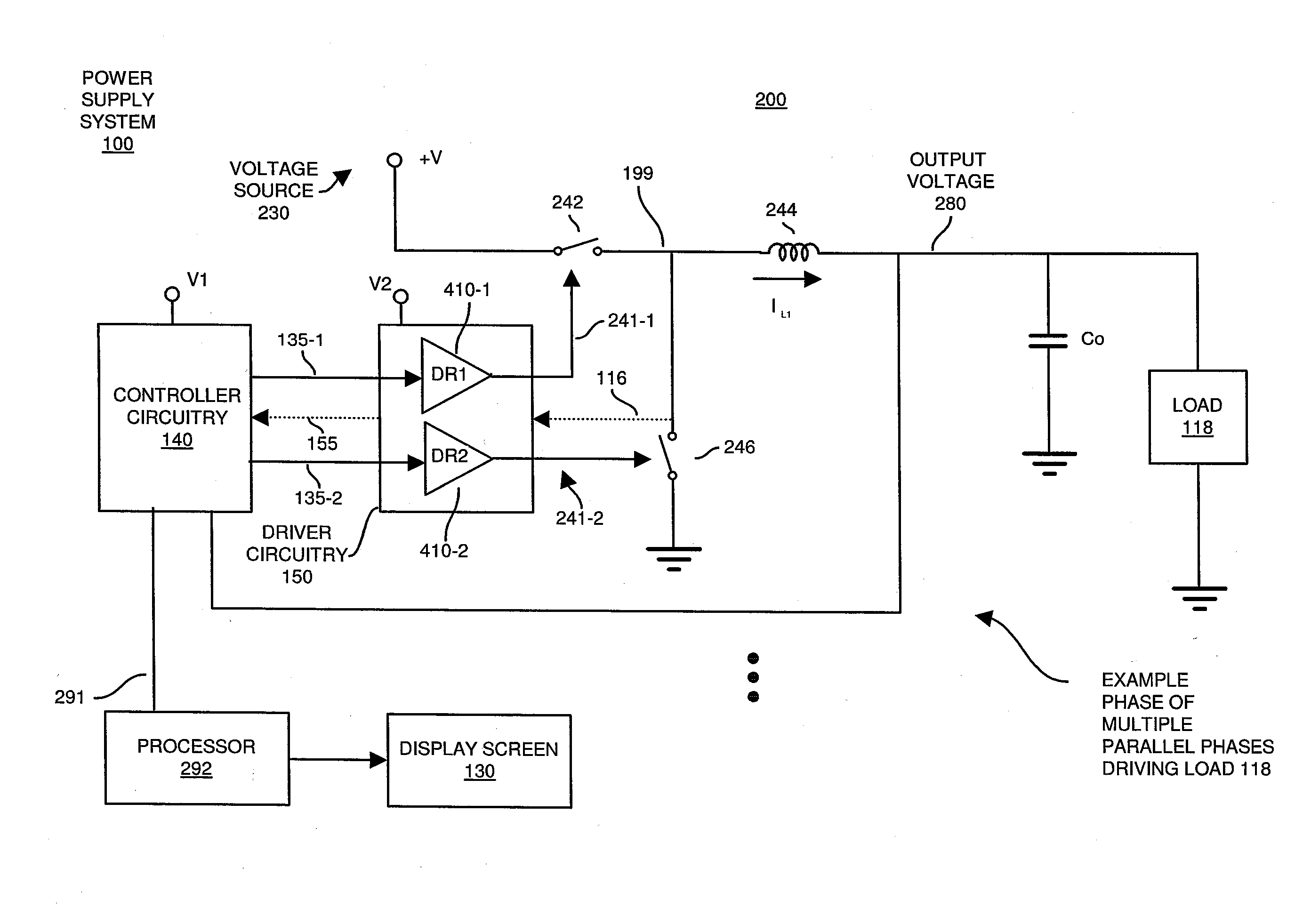
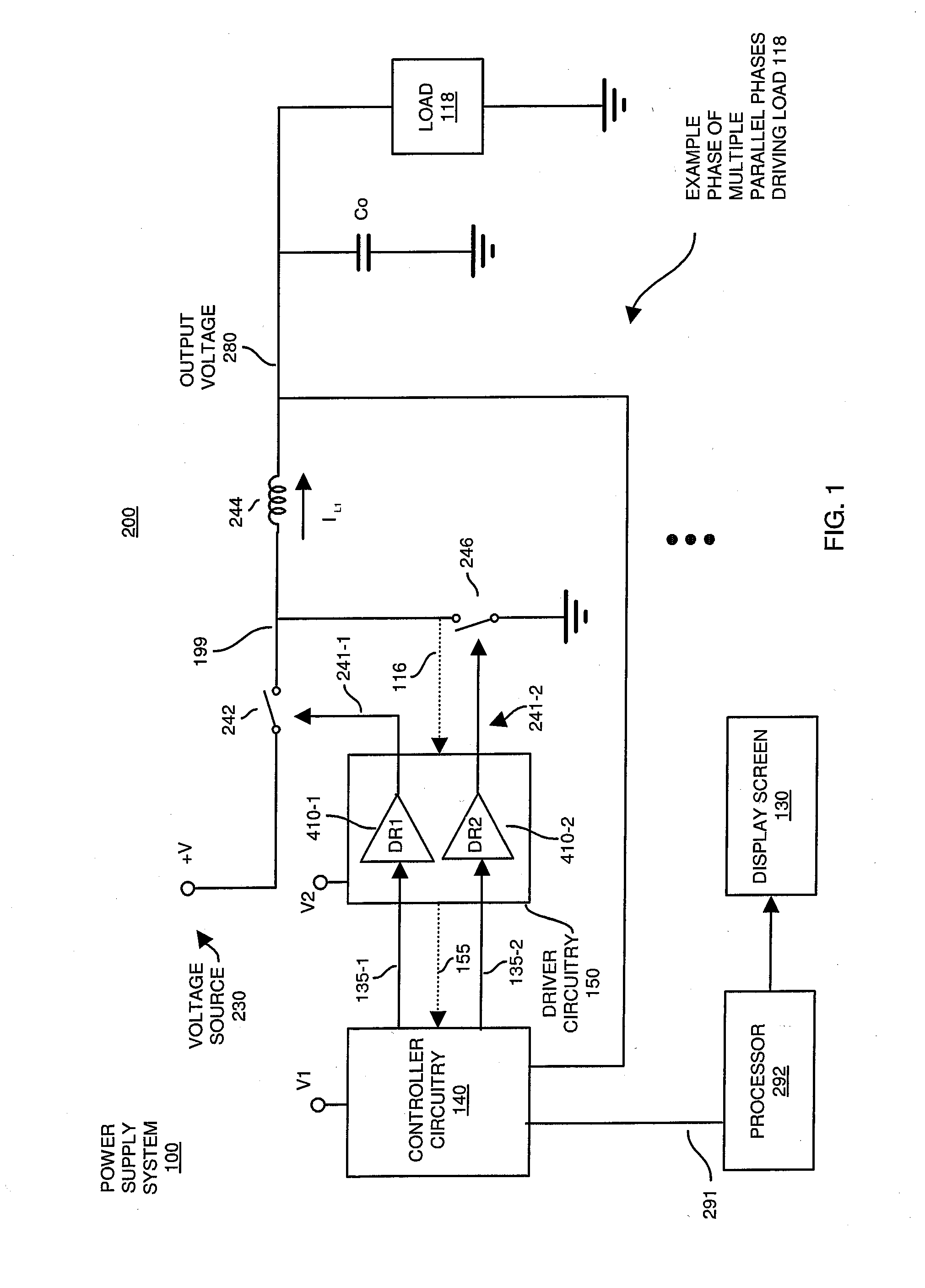
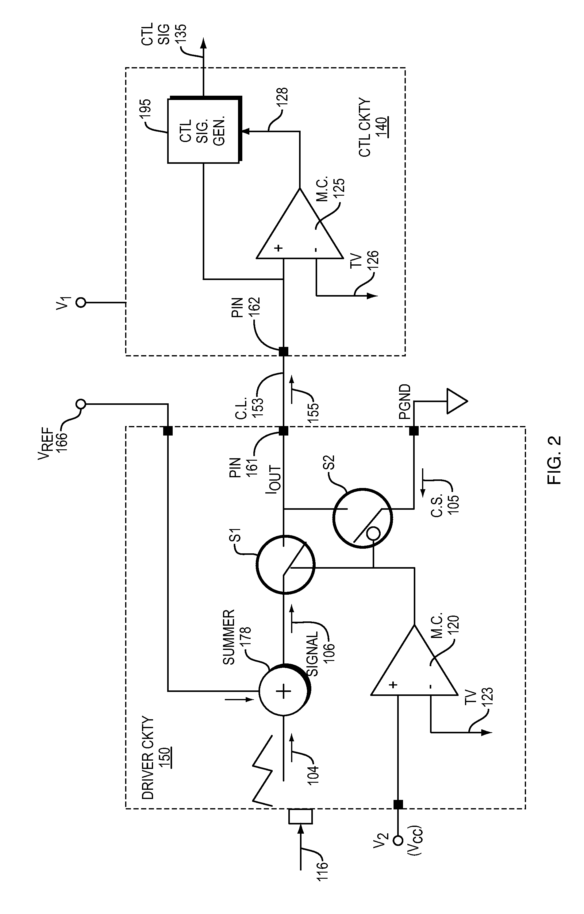
[0032]In accordance with embodiments herein, a system comprises first circuitry (such as a first integrated circuit device having a limited number of input / output pins) and second circuitry (such as a second integrated circuit device having a limited number of input output pins). The second circuitry is communicatively coupled to receive communications over a communication link from the first circuitry. In one embodiment, the first circuitry includes a monitor circuit. The monitor circuit monitors a voltage rail inputted to power the first circuitry. The monitor circuit initiates switching between transmitting a control signal (such as status information indicating whether the first circuitry is powered correctly) and a data signal over a communication link from the first circuitry to second circuitry depending upon the magnitude of the voltage rail. For example, when the first circuit is properly powered, the monitor circuit initiates transmission of the data signal over the commun...


PUM


Abstract

An example system comprises first circuitry (such as a first integrated circuit device having a limited number of input/output pins) and second circuitry (such as a second integrated circuit device having a limited number of input output pins). The second circuitry is communicatively coupled to receive communications over a communication link from the first circuitry. In one embodiment, the first circuitry includes a monitor circuit. The monitor circuit monitors a voltage rail inputted to power the first circuitry. The monitor circuit initiates switching between transmitting a control signal (such as status information indicating whether the first circuitry is powered correctly) and a data signal over a communication link from the first circuitry to second circuitry depending upon the magnitude of the voltage rail. For example, when the first circuit is properly powered, the monitor circuit initiates transmission of the data signal over the communication link to the second circuitry.

Description

BACKGROUND[0001]In multi-circuit applications powered by multiple voltage rails, it is sometimes necessary to guarantee that the power sequencing is maintained between two or more independent circuits. For example, a first circuit powered by a first voltage rail may be communicatively coupled to a second circuit powered by a second voltage rail. It may be necessary that the first voltage rail properly power the first circuit before the second circuit uses an output of the first circuit as valid input for further processing.[0002]Many times it is not possible to control a sequence of ramping voltage rails powering different circuits because the voltage rails are generated independent of each other. Because of this condition, it is possible that the second circuit in the above example is powered in advance of the first circuit. In such an instance, if the second circuit uses the output of the improperly powered first circuit, the second circuit will be processing invalid data.[0003]In...

Claims


Application Information

Patent Timeline
Patent Type & Authority Applications(United States)
IPC IPC(8): G01R19/165H02M3/158G01R19/00
CPCG01R19/16538H02M3/158G01R19/0084
Inventor KASTURI, PRASANRENGANATHAN, RAKESHCLAVETTE, DANNYGUO, RONG
Owner INFINEON TECH AMERICAS CORP
Why Eureka
Try Eureka