Centrifugal-pendulum vibration absorbing device

Inactive Publication Date: 2016-06-09
AISIN AW CO LTD
View PDF12 Cites 6 Cited by
  • Summary
  • Abstract
  • Description
  • Claims
  • Application Information

AI Technical Summary

Benefits of technology

[0023]In the centrifugal-pendulum vibration absorbing device according to the present disclosure, each of the mass bodies may be supported by the support member so as to be swingable about a pendulum fulcrum and rotatable about a center of gravity. This makes it possible to damp vibration to b

Problems solved by technology

Therefore, depending on the shape of the cushioning member, the cushioning member may be caught between the support member and the plate bodies of each of the

Method used


Image

  • Centrifugal-pendulum vibration absorbing device
  • Centrifugal-pendulum vibration absorbing device
  • Centrifugal-pendulum vibration absorbing device

Examples


Embodiment Construction

[0037]Now, a mode for carrying out the present disclosure will be described by way of an embodiment.

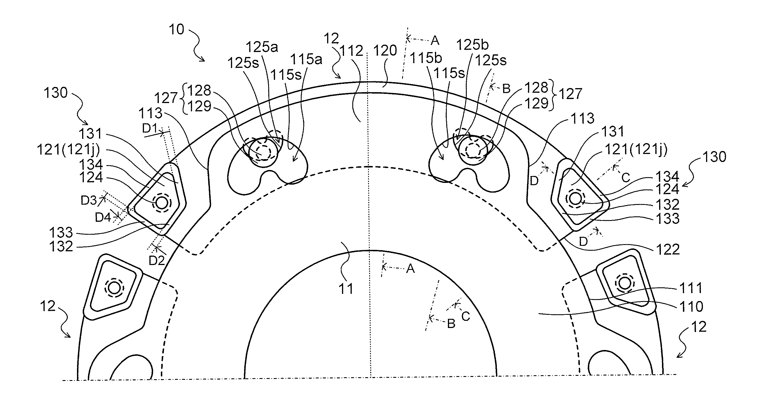
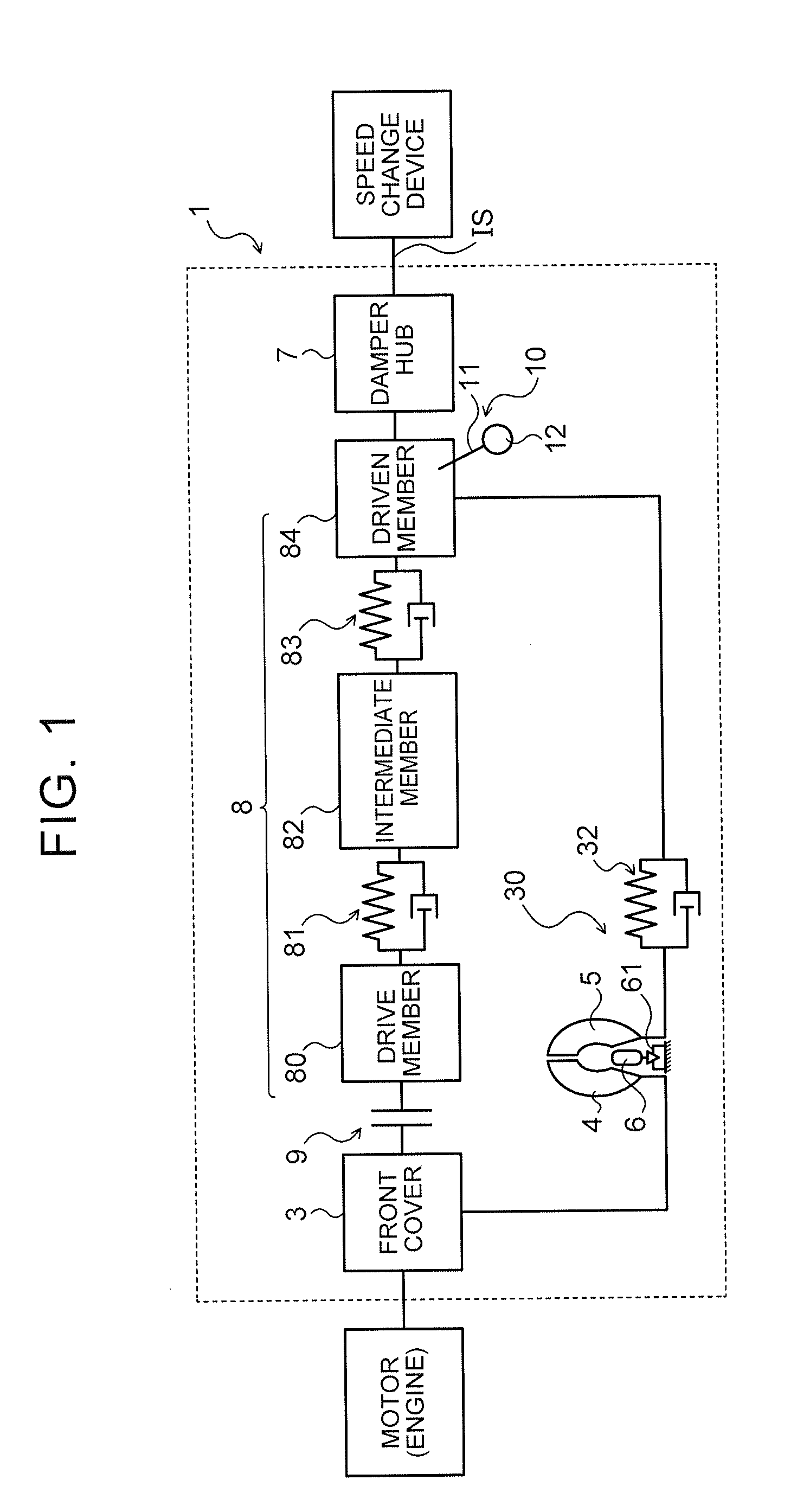
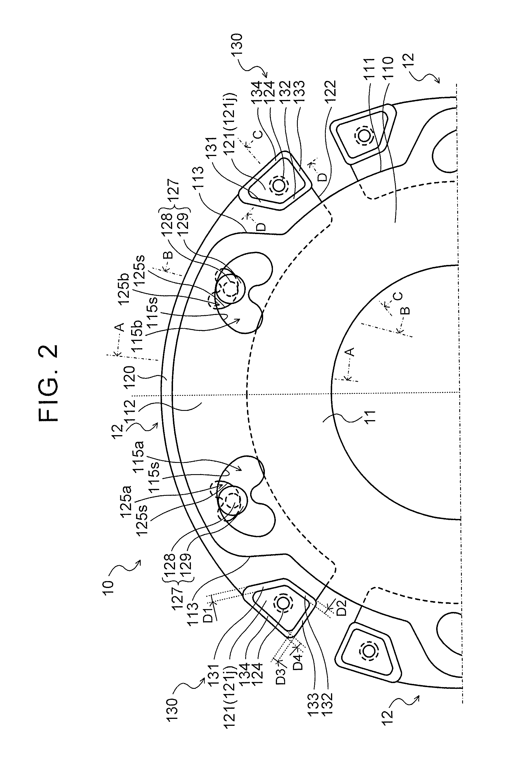
[0038]FIG. 1 is a diagram illustrating a schematic configuration of a starting device 1 that includes a centrifugal-pendulum vibration absorbing device 10 according to an embodiment of the present disclosure. FIG. 2 illustrates a schematic configuration of the centrifugal-pendulum vibration absorbing device 10. FIGS. 3 to 6 are an A-A sectional view, a B-B sectional view, a C-C sectional view, and a D-D sectional view illustrating an A-A section, a B-B section, a C-C section, and a D-D section, respectively, of the centrifugal-pendulum vibration absorbing device 10 of FIG. 2.

[0039]As illustrated in the drawings, a starting device 1 according to the embodiment is mounted on a vehicle, and constituted as a device that transmits power from an engine (internal combustion engine) that serves as a motor to an automatic transmission (AT) or a continuously variable transmission (CVT) that ser...


PUM


Abstract

A cushioning member between plate bodies of a mass body and at end portions, in the circumferential direction, so as not to rotate relative to the plate bodies. The peripheral edges, on both sides in the width direction, of the outer peripheral surfaces of the cushioning member's first and second side portions abutting against a support member, along with swing of the mass body, are chamfered, reducing the possibility that the cushioning member enters in a clearance between the side surfaces of the support member and the plate bodies when the cushioning members' first side portion and the support member abut, or when the cushioning member's second side portion and the support member abut, along with swing of the mass body, suppressing damage to the cushioning member.

Description

TECHNICAL FIELD[0001]The present disclosure relates to a centrifugal-pendulum vibration absorbing device.BACKGROUND ART[0002]There has hitherto been proposed a centrifugal-pendulum vibration absorbing device that includes a support member attached to a rotary element and a plurality of mass bodies each swingably supported by the support member and disposed adjacent to each other in the circumferential direction (see Patent Document 1, for example). In the centrifugal-pendulum vibration absorbing device, each of the mass bodies includes two arcuate plate bodies that face each other via the support member, and a cushioning member is attached at both end portions, in the circumferential direction, of the plate bodies to reduce a shock of collision between the mass bodies.RELATED-ART DOCUMENTSPatent Documents[0003][Patent Document 1] German Patent Application Publication No. 10 2011 013 232 A1SUMMARY[0004]Besides the configuration discussed above, there is also considered a centrifugal-...

Claims


Application Information

Patent Timeline
IPC IPC(8): F16F15/14
CPCF16F15/145
Inventor TAKIKAWA, YOSHIHIROOI, YOICHIMIYAOKA, TAKAYUKIHIRAI, YUICHIRO
Owner AISIN AW CO LTD
Why Eureka
Try Eureka